


Raspberry Pi Pico[2] + W5500
Overview
This tutorial demonstrates how Mongoose Library can be used on an RP2040- or RP2350-based board with the addition of a W5500 chip, using Mongoose's built-in TCP/IP stack.
Features of this implementation include:
- Uses the Raspberry Pi Pico-SDK
- Uses Mongoose's built-in TCP/IP stack, which includes a W5500 driver
- Does NOT use an external network stack like lwIP, or RTOS like FreeRTOS
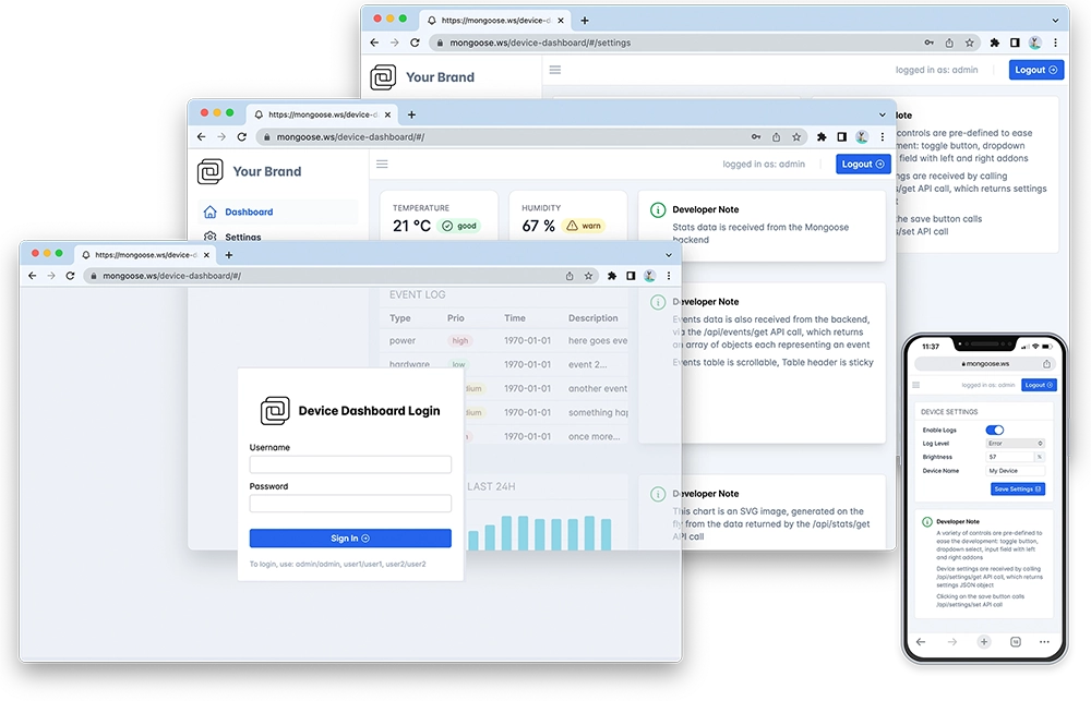
- The Web dashboard provides:
- User Authentication: login protection with multiple permission levels
- The web UI is optimised for size and for TLS usage
- Logged users can view/change device settings
- The web UI is fully embedded into the firmware binary, and does not need a filesystem to serve it, making it resilient
This example is a hardware adaptation of the Device Dashboard that can run on Mac/Linux/Windows. Mongoose Library, being cross-platform, allows to develop and run the same code on different platforms. That means: all functionality related to networking can be developed and debugged on a workstation, and then run as-is on an embedded device - and this example is a demonstration of that.
This example uses the Pico-SDK and compiles with its standard toolchain, it has the following files:
- main.c: provides the
main()entry point with hardware init and LED blinking, , SPI low-level and pin initialization code, initializing the network, and calling the event manager - CMakeLists.txt - A cmake file that selects the source files and compilation options
- Makefile- mainly pulls the SDK from its Github repo and calls cmake
mongoose.c,mongoose.h- Mongoose Librarynet.c,net.h- part of the device dashboard example, contains the Web functionalitypacked_fs.c- part of device dashboard example, embeds the Web UI used by the dashboard
Below is a general process outline:
- The board IP addressing will be provided by a DHCP server. If you want to set a static configuration, set IP address, network mask and gateway in
main.c; see below - Build the example (see below) and run it on a development board
- The firmware initializes the network
- After initialization, the application starts Mongoose's event loop and blinks an LED
- Once the LED starts blinking, the example is ready
- Open your web browser and navigate to the board IP address, you should see a nice device dashboard
Board options
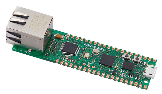
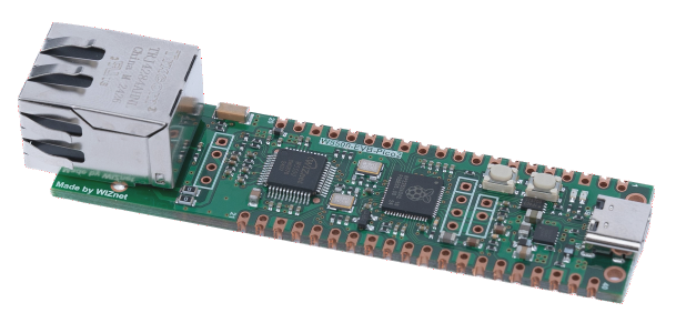
You can use either a board like the W5500-EVB-Pico, that has an RP2040 and a W5500 with an Ethernet jack, or a W5500-EVB-Pico2, that has an RP2350 and a W5500 with an Ethernet jack, or you can use for example a Raspberry Pi Pico or Pico 2 wired to an add-on board with the W5500.
W5500-EVB-Pico and W5500-EVB-Pico2
The default SPI pin selection is just for these boards:
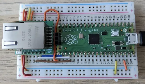
mini W5500 add-on
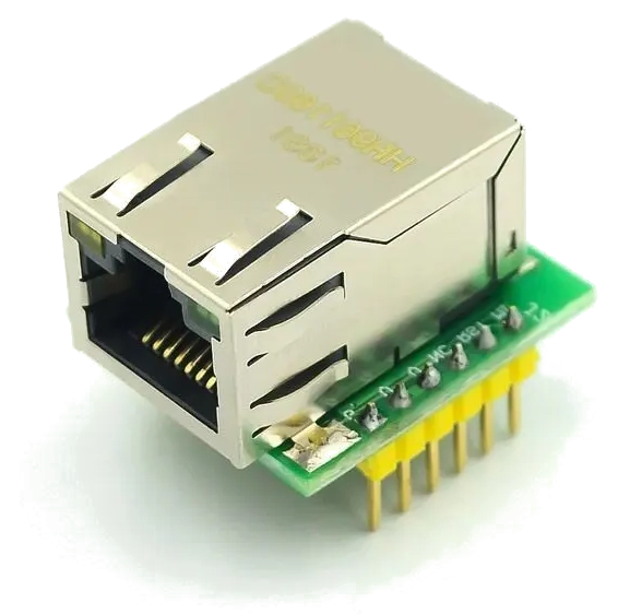
With a board like this one, you have to wire the SPI interface and power connections between the boards:
| W5500 | Raspberry Pi Pico [2] | ||
|---|---|---|---|
| 1, 2, 12 | GND | GND | 38 |
| 3 | MOSI | GPIO19/SPI0_TX | 25 |
| 4 | SCLK | GPIO18/SPI0_SCK | 24 |
| 5 | SCNn | GPIO17/SPI0_CSn | 22 |
| 7 | MISO | GPIO16/SPI0_RX | 21 |
| 10, 11 | 3.3V | 3V3 | 36 |
The Pico, powered from USB, will provide 3.3V to the add-on board through its built-in step-down power supply
This is the end result:
W5500 add-on
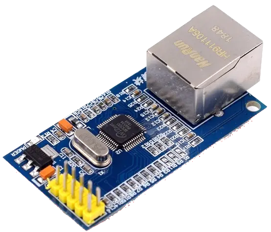
With a board like this one, you also have to wire the SPI interface and power connections between the boards:
| W5500 | Raspberry Pi Pico [2] | ||
|---|---|---|---|
| 1, 7 | GND | GND | 38 |
| 2 | SCLK | GPIO18/SPI0_SCK | 24 |
| 4 | SCS | GPIO17/SPI0_CSn | 22 |
| 6 | MOSI | GPIO19/SPI0_TX | 25 |
| 8 | MISO | GPIO16/SPI0_RX | 21 |
| 10 | 3.3V | 3V3 | 36 |
With this wiring, the Pico, powered from USB, will provide 3.3V to the add-on board. You can also power this board with a 5V source, which you can also take from the Pico. However, good practices dictate that you add series resistors on every signal connection, as the RP2040 and the W5500 will have different 3.3V power supplies that will not match. So, we recommend you follow the wiring suggested above.
Other RP2040- or RP2350-based boards
If you choose to use any other board, either mimic the wiring above or change this line in main.c accordingly:
Build and run
- Follow the Build Tools tutorial to setup your development environment.
- Start a terminal in the project directory; and clone the Mongoose Library repo, and run the
makecommand:git clone https://github.com/cesanta/mongoose cd mongoose/tutorials/pico-sdk/w5500-evb-pico-picosdk-baremetal-builtin/ - For testing purposes, the example defaults to using a UART for stdio, to be able to connect via USB as detailed below, modify these two lines in
CMakeLists.txt: - Run the
make buildcommand:make build - Once the build succeeds, boot your Pico in USB Mass Storage Mode by holding down the
BOOTSELbutton while you plug it into the USB port. Once it is connected, then release theBOOTSELbutton. It should automatically mount as a new USB disk in your machine. Now either manually copy or drag and drop the generatedexample.uf2file into this new USB disk device. - The Pico will flash this code and reboot, unmounting this disk and running the flashed code.
- Now open a second terminal, this will be our serial console to see the logs. Run a serial port software (we use picocom; make sure you configure it at 115200bps and to add a carriage return). Device name is usually
/dev/ttyACM0. Wait a bit and plug your network cable:picocom /dev/ttyACM0 -i -b 115200 picocom v2.2 ... 5dc3 2 main.c:79:main Ethernet: down, IP: 0.0.0.0, ... ... 667d 2 mongoose.c:6749:onstatechange READY, IP: 192.168.0.24 667e 2 mongoose.c:6750:onstatechange GW: 192.168.0.1 6680 2 mongoose.c:6752:onstatechange Lease: 86062 sec 697b 2 main.c:79:main Ethernet: ready, IP: 192.168.0.24, ... - Now start a browser on
http://IP_ADDRESS, whereIP_ADDRESSis the board's IP address printed on the serial console or checked on your DHCP server. You should see a login screen as in the image above
NOTE: For the RP2350-based boards, you need to use Pico-SDK 2.0.0 and provide the board type when calling cmake; in the example Makefile:
    cd build && cmake -DPICO_BOARD=pico2 -G "Unix Makefiles" .. && make

pico-sdk:
    git clone --depth 1 -b 2.0.0 https://github.com/raspberrypi/pico-sdk $@
There is a ready-made example for the W5500-EVB-Pico2 here
- From here on, if you want to try the dashboard features please go to the device dashboard tutorial and follow some of the steps depicted there.
Compilation options
Network operations need a time base to calculate timeouts; this, as well as random number generation, will be provided by the SDK, and Mongoose needs to know how to link to them. We define these and other compilation options in mongoose_config.h
MG_ARCH = MG_ARCH_PICOSDK- configures Mongoose to work with Raspberry Pi's Pico-SDKMG_ENABLE_TCPIP = 1- enables the built-in TCP/IP stackMG_ENABLE_DRIVER_W5500- enables the built-in driver for the W5500
main.c overview
This example can be divided in the following blocks:
- Initialize the microcontroller for this particular board
- Initialize Mongoose
- Initialize the networking stack
- Run Mongoose
MCU and board initialization
We call SDK functions to initialize the MCU, stdio, and those peripherals we are going to use:
SPI initialization
The SPI initialization follows. We need to enable the GPIO pins to connect to the W5500:
Mongoose initialization
Then we initialize Mongoose, this is no different from what we always do in any example.
There is also a timer that we use to blink the LED and print the link stats
For more information on timers, check the timers tutorial.
TCP/IP initialization
The TCP/IP stack has to be enabled to be compiled in, and so Mongoose will work in association with it. This is done in the CMakeLists.txt file by defining MG_ENABLE_TCPIP=1.
Then this networking stack has to be configured and initialized. This is done by calling mg_tcpip_init() and passing it a pointer to a struct mg_tcpip_if. Inside this structure:
- have pointers to a
struct mg_tcpip_driverand any extra data that it could need. - For DHCP: set
ipas zero - For a static configuration, specify
ip,mask, andgwin network byte order
In this example we use DHCP, but you can remove the comments and set a static configuration if you want:
Note that, we also need to specify a unique MAC address; this example provides a macro to transform the Pico board unique ID into a unicast locally administered address. For production runs you'll have to consider among several options, from adding a MAC address chip in your hardware design to registering with the IEEE Registration Authority.
Some drivers, as you have probably noticed, require extra data. In this case the W5500 driver needs to know which functions to call to perform SPI initialization and transfers, so we included pointers to those functions we described above
Run Mongoose
Then we run Mongoose. This is no different from what we always do in any example, though note that it should be run after network initialization. The logic is standard: initialize the event manager (as we already did), start a listener, and fall into an infinite event loop:
In this case, the listener is started by web_init(), the device dashboard initialization function. The URL is configured by the macro HTTP_URL, which we set in CMakeLists.txt.
We have covered those aspects that are specific to the STM32 implementation, for the details on the application and the UI, please see the Device Dashboard tutorial.
SPI low-level functions
We provide a basic set of functions to do transactions, that is, a couple of functions to begin and end the transaction (enable and disable chip select) and a third function to transfer a byte (send one, receive one, simultaneously). These are of course wrappers to SDK functions: