


ESP32: UART Bridge
Overview
This tutorial shows an example of how to send UART data over the network using an ESP32. A real bridge can be built using two devices, though in this tutorial we'll only cover one side of it.
Since UART0 in the ESP32 is used for flashing, and logging, in order to interface to one of the other UARTs in the ESP32, we need to connect to two pins. In this example we'll be using UART1 in GPIOs 25 and 26, and we'll be using a USB-to-UART interface board so we can access that from our computer.
Since USB is a 5V interface, many of these boards have a VIO or VCCIO pin. This pin is the voltage supply for the I/O section of the interface chip (like those of the FT232 family, for example), and as the ESP32 in our module is working at 3.3V, we'll connect this (3V3 pin in many ESP32 modules) to our interface board too.
NOTE: If your board doesn't have a VIO pin, make sure it outputs 3.3V. In this case, it is good practice to put resistors in series with the TD and RD pins in order to limit any currents flowing due to the power supply voltage difference between this USB-to-UART board and the ESP32 module.

PAY ATTENTION: Make sure your interface board does NOT output RS-232 levels, otherwise you'll burn the ESP32 GPIOs.
This tutorial is a hardware example following on the UART bridge tutorial. You should read and follow that tutorial first.
Check the ESP32 device dashboard tutorial for a bit of extra information on the typical ESP-IDF project structure.
Build and try
If you've not already done so, clone the Mongoose Library repo
$ git clone https://github.com/cesanta/mongooseThis example requires you have Docker installed and your user is able to run it. If in doubt, check
$ docker psBuild the example. Unless you already have an ESP-IDF image, this will download it, what will take some time. The first build process also takes a while.
$ cd mongoose/tutorials/http/uart-bridge/esp32
$ make build
...
Successfully created esp32 image.
Generated [...]/mongoose/tutorials/http/uart-bridge/esp32/build/mongoose-esp32-example.bin
...
Project build complete. To flash, run this command:
...
Now let's flash it. We need to know the device name for the serial port that was assigned to the ESP32. If it is the only USB serial port we have, it will usually be
/dev/ttyUSB0. Plug your ESP32 board first, wait a couple of seconds and then plug your USB-to-UART interface board. If you have esptool.py installed, you can run the command shown in the former action; here, we will use make:$ make flash PORT=/dev/ttyUSB0 ... Hash of data verified. Leaving... Hard resetting via RTS pin... ESP32 Running ninja in directory /home/username/mongoose/tutorials/http/uart-bridge/esp32/build Executing "ninja flash"... DoneNow let's connect to the ESP32 board, in this example we'll be using minicom; make sure you configure it for 115200bps. You can also download and unzip esputil, in that case you can run
make flash2 PORT=/dev/ttyUSB0in the prior step oresputil -p /dev/ttyUSB0 monitornow. Let's reset our board and see how it starts:$ minicom -D /dev/ttyUSB0 ... I (477) cpu_start: Application information: I (482) cpu_start: Project name: mongoose-esp32-example I (488) cpu_start: App version: 1 ... I (572) cpu_start: Starting scheduler on PRO CPU. I (0) cpu_start: Starting scheduler on APP CPU. 2a 2 main.c:21:app_main FS at /spiffs initialised, status: 0 2c 2 main.c:34:app_main WiFi is not configured, running CLI. Press enterThe first time we flash it, there won't be a WiFi configuration, so we'll use a small CLI built into the firmware to configure it. As the CLI has no echo, we can configure our serial port software for local echo; in minicom is
<CTRL-A> E. Now press the enter key as instructed:--- CLI command: '' --- Unknown command. Usage: --- set NAME VALUE --- rm FILENAME --- cat FILENAME --- ls --- reboot --- wifi WIFI_NET WIFI_PASS --- CLI output endWe can now enter our WiFi SSID and password
wifi mynet mypass

c9ea 2 wifi.c:45:event_handler          IP ADDRESS: 192.168.69.231. Go to:
c9ee 2 wifi.c:46:event_handler          http://192.168.69.231
c9f4 2 wifi.c:93:wifi_init              connected to ap SSID:mynet
ca03 2 cli.c:7:cli_wifi                 Reboot now
--- CLI output end
Let's reset our board again and see how it starts:
...
I (1030) wifi:connected with mynet, aid = 2, channel 11, BW20, bssid = 96:f6:52:a4:c0:1e
I (1030) wifi:security: WPA2-PSK, phy: bgn, rssi: -56
I (1030) wifi:pm start, type: 1
...
I (2660) esp_netif_handlers: sta ip: 192.168.69.231, mask: 255.255.255.0, gw: 192.168.69.1
817 2 wifi.c:45:event_handler           IP ADDRESS: 192.168.69.231. Go to:
81c 2 wifi.c:46:event_handler           http://192.168.69.231
821 2 wifi.c:93:wifi_init               connected to ap SSID:mynet
827 2 main.c:46:app_main                Mongoose v7.7 on http://0.0.0.0:80
832 2 net.c:151:config_apply            Applying config: {"tcp":{"url":"tcp://0.0.0.0:4001","enable":true},"ws":{"url":"ws://0.0.0.0:4002","enable":true},"mqtt":  {"url":"mqtt://broker.hivemq.com:1883?tx=b/tx&rx=}
847 2 uart.c:22:uart_open               1: 25/26/115200, 0 0 0
84a 3 net.c:206:mg_listen               1 0x36 http://0.0.0.0:80
878 3 net.c:206:mg_listen               2 0x37 tcp://0.0.0.0:4001
87b 3 net.c:206:mg_listen               3 0x38 ws://0.0.0.0:4002
Now start your browser and point it to the IP address reported, in our case is
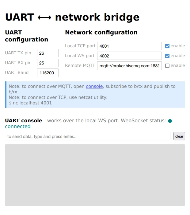
http://192.168.69.231as can be seen above, yours will depend on your network and how your Access Point DHCP server is configured. The main page is loaded; the JavaScript code on the web page GETs the configuration from/api/config/get, renders the UI, and connects to the WebSocket server (if enabled). The default configuration has random pin numbers for the serial I/O, let's put the pins we are using, in our case 26 and 25 as seen on the picture.
Let's reset our board one last time and see how it starts. You should see the same messages as before, but if you enabled MQTT you'll see some extra messages as the board resolves the broker address and tries to connect to it.
Now open a second terminal on which to run another copy of a serial port software (we use minicom; make sure you configure it for 115200bps or the speed you may have set), this time to connect to the USB-to-UART board and through it to the ESP32. Check your board's device name.
$ minicom -D /dev/ttyUSB1Type anything on this terminal window, you'll see that rendered on the UI.
Conversely, write something on the UI as instructed, and you'll see it at the terminal window. The first terminal will be showing these actions on the log.
From here on, please go to the UART bridge tutorial and repeat some of the steps depicted there
- You can manually connect to the WebSocket server with a WebSocket client like for example wscat
$ wscat --connect localhost:4002 Connected (press CTRL+C to quit) < - You can connect to the TCP server with a client like for example nc
$ nc localhost 4001 - If you enable the MQTT client, you can send a message to the device via MQTT using any MQTT client, for example mosquitto_pub, by publishing to the configured topic:
$ mosquitto_pub -h broker.hivemq.com -t "b/rx" -m "hello" - With any MQTT client, you can subscribe to the configured topic and receive what enters the UART:
$ mosquitto_sub -h broker.hivemq.com -t "b/tx"
- You can manually connect to the WebSocket server with a WebSocket client like for example wscat
How it works
Here we'll cover those aspects that are specific to the ESP implementation, for the details on the application and the UI, please see the UART bridge tutorial.
UART
The HAL uses a set of functions to read, write, and initialize the UART:
In order to include the actual UART implementation, we need to define the UART_API_IMPLEMENTED macro, as can be seen on the common code
We do that at the component level CMake file, main/CMakeLists.txt:
The driver uses generic code, we also need to configure which UART we'll be using; we do that in main.h:
The driver itself is mainly a wrapper to the ESP-IDF UART API:
Configuration
The HAL uses a set of functions to read and write the configuration to a non-volatile medium:
In order to include our actual files, we need to define the UART_API_IMPLEMENTED macro, as we've seen above. The configuration will be stored in a filesystem on the device.
The driver itself is mainly a wrapper to the Mongoose filesystem API. The ESP-IDF provides a POSIX filesystem support, so we use that. The macro FS_ROOT is defined in main.h and points to the SPIFFS partition: /spiffs
main
We mount the SPIFFS partition and try to read the WiFi credentials file. Since it is in JSON format, we parse its contents using Mongoose's JSON API and initialize WiFi, to finally initialize the event manager and call it in an infinite loop.
Otherwise, we run the CLI, passing it whatever chars the user enters on the flashing/debugging serial port. The CLI itself is very simple, it buffers characters until the user hits the enter key, then compares to a set of strings to perform simple tasks. The most important is of course wifi that allows us to enter proper credentials for our WiFi network, initializing WiFi and saving them to the WiFi configuration file:
Here, the %m specifier for mg_file_printf() calls mg_print_esc() that simplifies printing JSON strings.