


ESP32: Device Dashboard
Overview
This tutorial demonstrates how Mongoose Library can be used to implement a device dashboard on an ESP32.
Features of this implementation include:
- Uses the ESP-IDF framework
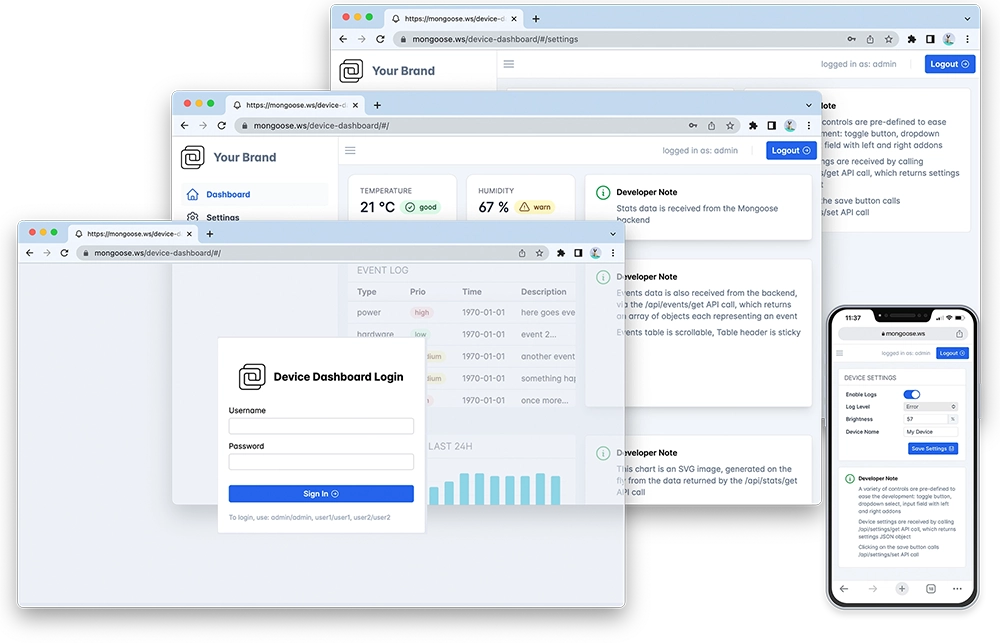
- The Web dashboard provides:
- User Authentication: login protection with multiple permission levels
- The web UI is optimised for size and for TLS usage
- Logged users can view/change device settings
- The web UI is fully embedded into the firmware binary, and does not need a filesystem to serve it, making it resilient
This example is a hardware adaptation of the Device Dashboard that can run on Mac/Linux/Windows. Mongoose Library, being cross-platform, allows to develop and run the same code on different platforms. That means: all functionality related to networking can be developed and debugged on a workstation, and then run as-is on an embedded device - and this example is a demonstration of that.
Take your time to navigate and study the Device Dashboard tutorial. Here, we concentrate on the features specific to this embedded platform.
This example uses the ESP-IDF 4.x/5.x toolchain, and therefore the project structure follows a standard ESP-IDF CMake-based format:
main/- a "main" component directory which includes application code- main/CMakeLists.txt - a standard ESP-IDF component-level project CMake file
- main/main.c - main application file, contains Mongoose logic
- main/wifi.c - contains Wifi setup routine,
wifi_init() main/mongoose.c,main/mongoose.h- Mongoose Librarymain/net.c,main/net.h- part of the device dashboard example, contains the Web functionalitymain/packed_fs.c- part of device dashboard example, embeds the Web UI used by the dashboard
- CMakeLists.txt - a standard ESP-IDF top-level project CMake file
- partitions.csv - defines a partition table for the flash
- sdkconfig.defaults - default build values
- Makefile - mainly invokes Docker to call the IDF utilities
Build and run
Before building the project, open the main/main.c file and edit your WiFi network
name and WiFi password settings:
The next step is to build the project. It is assumed you're using Linux or Mac as a workstation, you have Docker installed, and your user is able to run it. If in doubt, check
$ docker ps
Start a terminal in the project directory; clone the Mongoose Library repo,
and run the make build command:
$ git clone https://github.com/cesanta/mongoose
$ cd mongoose/tutorials/http/device-dashboard/esp32
$ make build
In order to flash this recently built firmware to your ESP32 board, plug it in a USB port
and execute (change /dev/ttyUSB0 to the actual serial port for your module, on your system):
$ make flash PORT=/dev/ttyUSB0
You can also download and unzip esputil, in that case run make flash2 PORT=/dev/ttyUSB0. When done, connect to the serial console. You can use a serial port application like minicom or you can also use esputil, just run esputil -p /dev/ttyUSB0 monitor.
Now start a browser on http://IP_ADDRESS where IP_ADDRESS is the board's IP address printed on the serial console. You should see a login screen.
From here on, please go to the device dashboard tutorial and repeat some of the steps depicted there
Build with TLS support
To build using MbedTLS, just configure Mongoose to enable it, the IDF already builds it for us:
- In
main/mongoose_config.h, defineMG_TLStoMG_TLS_MBED
Compilation options
Network operations need a time base to calculate timeouts; this, as well as random number generation, will be provided by the IDF, and Mongoose needs to know how to link to them. We define these and other compilation options in mongoose_config.h
MG_ARCH = MG_ARCH_ESP32- configures Mongoose to work with Espressif's IDF for the ESP32MG_ENABLE_PACKED_FS = 1- enables the embedded filesystem support
main.c overview
This example can be divided in the following blocks:
- Mount a filesystem and write a sample file
- Initialise WiFi
- Run Mongoose
Mount filesystem
The firmware that has been built does not have a filesystem image flashed, but it has SPIFFS filesystem support. So the following piece of code initialises a filesystem, and writes a file hello.txt using the mg_file_printf() API call.
For this example we've chosen to embed all the web files in a packed filesystem, more information on the embedded filesystem tutorial
Initialise Wi-Fi
There we call a wifi_init() function which is defined in main/wifi.c. That is a blocking function, i.e. it does not return until the board gets an IP address:
Run Mongoose
Next goes Mongoose. Note that it should be run after network initialisation is complete - which is true in our case. The logic is standard - initialise the event manager, start a listener, and fall into an infinite event loop:
We have covered those aspects that are specific to the ESP implementation, for the details on the application and the UI, please see the device dashboard tutorial.
Using SPIFFS to store web files
In case we'd like to hold our web files on a partition using the SPIFFS filesystem, here is an example on how to do it.
This event handler function shows a RESTful handler with the /api/state URI, which reports the amount of
free RAM. Other URIs are treated as static server requests:
There is a caveat there - we redefine FS handler. This is done because
SPIFFS is a flat file system without directory support. Therefore we
create our own filesystem which is derived from a standard POSIX FS but has
a stat() function redefined - it returns a "directory" flag for /:
Configure for your module
DevkitC boards can have different ESP32-WROOM module options with different ESP32 processors and memory sizes at different speeds.
This example is configured for a bare minimum in order to run in as many devices as possible, if you want to tweak the settings for your device, change the settings in the sdkconfig.defaults file.
M5 STAMP PICO
The M5 STAMP PICO has 4MB flash connected via SPI at 80MHz, with the ESP32-PICO-D4 processor clocked at 240MHz:
# These are specific for ESP32-PICO-D4
CONFIG_ESPTOOLPY_FLASHFREQ_80M=y
CONFIG_ESPTOOLPY_FLASHFREQ="80m"
CONFIG_ESPTOOLPY_FLASHSIZE_4MB=y
CONFIG_ESPTOOLPY_FLASHSIZE="4MB"
CONFIG_ESP32_DEFAULT_CPU_FREQ_240=y
CONFIG_ESP32_DEFAULT_CPU_FREQ_MHZ=240
XIAO-ESP32-C3
The XIAO-ESP32-C3 has 4MB flash connected via SPI at 80MHz, with the ESP32-C3 processor clocked at 160MHz. It uses a RISC V processor, so these changes are mandatory in order to compile for the right processor architecture:
# These are specific for ESP32-C3(Fx4)
CONFIG_IDF_TARGET_ARCH_RISCV=y
CONFIG_IDF_TARGET="esp32c3"
CONFIG_IDF_TARGET_ESP32C3=y
CONFIG_ESP_DEFAULT_CPU_FREQ_MHZ_160=y
CONFIG_ESP_DEFAULT_CPU_FREQ_MHZ=160
CONFIG_ESPTOOLPY_FLASHFREQ_80M=y
CONFIG_ESPTOOLPY_FLASHFREQ="80m"
CONFIG_ESPTOOLPY_FLASHSIZE_4MB=y
CONFIG_ESPTOOLPY_FLASHSIZE="4MB"
In a Linux system, the usual port name is /dev/ttyACM0, as the module uses the ESP32-C3 built-in USB serial
You will need an antenna connected to the module