


Web UI Device Dashboard
a complete guide
Overview
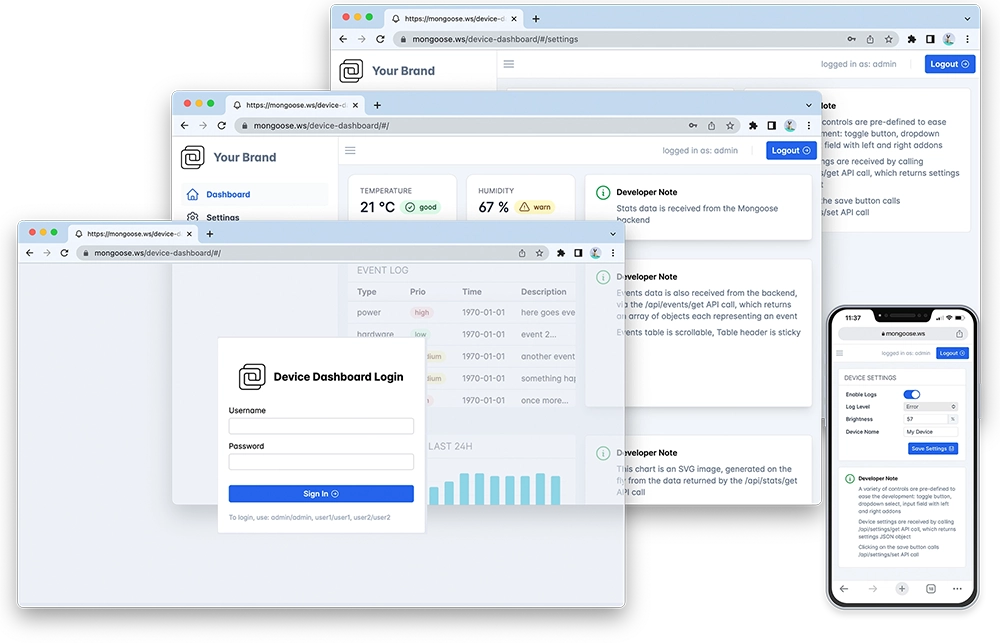
Web UI Dashboard is a very common functionality for connected devices. It is used to access devices easily, control devices, change device configuration, and update software on them.
Mongoose Library provides a complete Web UI Dasboard reference project. It is cross platform - works on any Windows/Mac/Linux workstation as well as on any embedded environment like STM32, NXP, Infineon, Renesas, and so on.
You can see it live, where it runs inside a Linux container on our website. If you have a network-enabled STM32 or NXP development board, we have built a very simple to use evaluation page, where you can build, flash, run and monitor directly in your browser - no installations or IDE required.
Below is a step-by-step practical guide on the implementation details, which explains all essential details about building embedded Web UI from scratch. At the end, you'll get the deep understanding of all the components, and have a working implementation blueprint. You'll be able to build Web UI of any complexity yourself, and get assistance from our team when required.
If you have any questions, please use our contact form or chat to use on our Discord chat.
Build and run - demo
Seeing something once is better than hearing about it a hundred times. Let's take a look at the end result - a working device dashboard. For the sake of simplicity, we will build and run it on a workstation - Mac, Windows or Linux. And later we will build up the same functionality from scratch on an embedded device. So, the steps are:
Step 1. Follow the Build Tools to setup your development
environment
Step 2. Clone mongoose repository to your workstation:
git clone https://github.com/cesanta/mongoose
Step 3. Build and run the example:
cd mongoose/tutorials/http/device-dashboard
make clean all
Step 3. Open http://localhost:8000 in your browser. Navigate through the UI - notice the login page, dashboard page, settings, events, firmware update. Open https://localhost:8443 and notice that HTTPS works, too.
That's what we're going to build now from scratch, and with every single step explained.
Action Plan
- Skeleton firmware: build a minimal firmware on a hardware board
- Integrate Mongoose: add Mongoose Library and make TCP/IP stack work
- Simple web server: add simple HTTP server - show a "hello world" page
- Simple web UI for LED control: enhance a simple web server
- add a Web UI for LED control
- learn how Web UI <-> device interaction works
- Complete web UI dashboard: implement a complete dashboard with
- user authentication (login page)
- metrics/graphs
- device settings page
- events / alerts page with pagination
- firmware update
1. Skeleton firmware
A skeleton firmware is a minimal firmware on a hardware board, which perform the minimum setup required for the reference projects:
- Set CPU clock to the maximum frequency,
- Set up LED pins to GPIO output mode, and blink an LED,
- Set up network hardware, e.g. initialise Ethernet pins,
- Set up UART and prints debug log on a console
Skeleton firmwares intentionally do not implement any extra functionality - for example, they do not setup RTOS. That is done for simplicity reasons, and to show / explain only things that are relevant to networking. That said, a production firmware should perform all required extra initialisation. Provided reference projects would function regardless.
The first step to build a reference project, is to create a skeleton firmware. For some architectures, we prepared step-by-step guides you can follow. For other architectures, please refer to the respective manuals to implement steps 1-4 mentioned above, or tell us to make a guide for it.
Skeleton firmware for STM32 F2/F4/F7/H5/H7 MCU with Ethernet MAC on Cube IDE
The table below summarises peripherals for various boards:
| Board | UART, TX, RX | Ethernet | LED |
|---|---|---|---|
| STM32H747I-DISCO | USART1, A9, A10 | A1, A2, A7, C1, C4, C5, G11, G12, G13 | I12, I13, I14 |
| STM32H735G-DK | USART3, D8, D9 | A1, A2, A7, C1, C4, C5, B11, B12, B13 | C3, C2 |
| STM32H573I-DK | USART1, A9, A10 | A1, A2, A7, C1, C4, C5, G11, G12, G13 | I8, I9, F1 |
| Nucleo-H563ZI | USART3, D8, D9 | A1, A2, A7, C1, C4, C5, B15, G11, G13 | B0, F4, G4 |
| Nucleo-H7S3L8 | USART3, D8, D9 | A2, A7, B6, G4, G5, G6, G11, G12, G13 | D10, D13, B7 |
| Nucleo-H745XI | USART3, B10, B11 | A1, A2, A7, C1, C4, C5, B13, G11, G13 | I13, J2, D3 |
| Nucleo-H735IG | USART3, D8, D9 | A1, A2, A7, C1, C4, C5, B11, B12, B13 | C3, C2, C2 |
| Nucleo-H755ZI-Q | USART3, D8, D9 | A1, A2, A7, C1, C4, C5, G11, G12, G13 | B0, E1, B14 |
| Nucleo-H743ZI | USART3, D8, D9 | A1, A2, A7, C1, C4, C5, B13, G11, G13 | B0, E1, B14 |
| Nucleo-H723ZG | USART3, D8, D9 | A1, A2, A7, C1, C4, C5, B13, G11, G13 | B0, E1, B14 |
| Nucleo-Fxxxxx | USART3, D8, D9 | A1, A2, A7, C1, C4, C5, B13, G11, G13 | B0, B7, B14 |
For a more verbose and in-depth description of STM32Cube IDE and the following steps, check this tutorial and CubeIDE Integration
Step 1. Start Cube IDE. Choose File / New / STM32 project
Step 2. In the "part number" field, type the microcontroller name,
for example "H743ZI". That should narrow down
the MCU/MPU list selection in the bottom right corner to a single row.
Click on the row at the bottom right, then click on the Next button
Step 3. In the project name field, type any name, click Finish.
Answer "yes" if a pop-up dialog appears
Step 4. A configuration window appears. Click on Clock configuration tab.
Find a field with a system clock value. Type the maximum value, hit enter,
answer "yes" on auto-configuration question, wait until configured
Step 5. Switch to the Pinout tab, Connectivity, then enable the UART controller
and pins (see table above), choose "Asynchronous mode"
Step 6. Click on Connectivity / ETH, Choose Mode / RMII, verify that the
configured pins are like in the table above - if not, change pins
Step 7. Click on System core / GPIO. Lookup LED pins from the table above.
For eaсh LED, click on the corresponding pin, select GPIO_output
Step 8. Click Ctrl+S to save the configuration. This generates the code
and opens main.c file
Step 9. Navigate to the main() function and add some logging to the
while loop. Make sure to insert your code between the "USER CODE" comments,
because CubeIDE will preserve it during code regeneration:
/* USER CODE BEGIN WHILE */
NVIC_EnableIRQ(ETH_IRQn);   // preferably do this in Cube, as the tutorials above instruct

while (1) {
  printf("Tick: %lu\r\n", HAL_GetTick());
  HAL_Delay(500);
Step 10. Redirect printf() to the UART. This is also called
"IO retargeting". ARM GCC is bundled with a C library called Newlib, developed
by RedHat. Newlib implements standard C IO functions like fopen(), fclose(),
fread(), fwrite(), fprintf(), printf() in a way that they call a low level
"syscall" functions - hence in Cube projects, there is a
file syscalls.c. Default syscalls implementations have weak linkage, so it
is possible to override a default with our own implementation. Let's do it for
the _write() syscall, that is called by printf(). Add the following snippet
right after the /* USER CODE BEGIN 0 */ line. Note that if the UART is other
that USART3, change the huart3 variable accordingly:
int _write(int fd, unsigned char *buf, int len) {
  if (fd == 1 || fd == 2) {                     // stdout or stderr ?
    HAL_UART_Transmit(&huart3, buf, len, 999);  // Print to the UART
  }
  return len;
}
Step 11. Add mg_millis() function that returns a number of milliseconds
since boot. This function will be required for accurate timer tracking. Add
it just below the _write() function:
uint64_t mg_millis(void) {
  return HAL_GetTick();
}
Step 12. Click on "Run" button to flash this firmware to the board.
Step 13. Attach a serial monitor tool (e.g. putty on Windows, or
cu -l COMPORT -s 115200 on Mac/Linux) and observe UART logs:
Tick: 90358
Tick: 90860
...
Our skeleton firmware is ready!
Skeleton firmware for STM32 F2/F4/F7/H5/H7 MCU with Ethernet MAC on Keil
For a more verbose and in-depth description of Keil uVision, how to take advantage of STM32Cube from within it, and the following steps, check this tutorial and this tutorial
Step 1. Install necessary packs. Start Keil, click on "Pack Installer" to start an installer. There in the search input, type "stm32f7", then click on "STM32F7 Series". On the right side of the window, you should see "Device Specific / Keil::STM32F7xx_DFP" pack, click on "Install" if it is not yet installed. When installed, install "Generic / Cesanta::Mongoose" pack
Step 2. Start a new project. Create a new project. In the Search filter, type "stm32f756zg", select first device. In the RTE window, check "Device/Startup", click on "Resolve", click OK.
Step 3. Create main.c. Right click on "Source group 1", "Add new file", "C file", type "main", click "Add". Copy/paste the following content, then save:
int main(void) {
  return 0;
}
Step 4. Update settings. Click on "Options for target" in the toolbar,
- On the "Device Target", check "Use MicroLIB"
- On the "User" tab, uncheck "Beep when complete"
- On the C/C++ tab, select Warnings / MISRA compatible
- On the Debug tab, select Use / ST-Link debugger
- Click on debugger "Settings", "Flash Download" tab, check "Reset and Run"
- Increase stack / heap size: open Project files / Device / startup_xxx.s, click on configuration wizard. Set stack to 8192, heap to 128000
Step 5. Build project. Click on "Build" toolbar button. The project should be built with zero errors and warnings.
Step 6. Configure the board. Instead of using CubeMX to configure clock, UART and LED, we'll copy a small HAL header and use it to achieve the same in a much quicker way.
- Open hal.h and copy file contents to the clipboard.
- Right click on "Source Group1", choose "Add new file", name it "hal.h", paste the contents, save
- Do the same for hal.c
- copy it into the project
- Update main.c code with the following:
#include "hal.h"

extern uint64_t mg_millis(void);

int main(void) {
  hal_init();     // you can also configure through STM32CubeMX, as shown in the tutorials above

  uint64_t timer = 0;
  for (;;) {
    if (timer < mg_millis()) {
      timer += 500;
      gpio_toggle(LED1);
      printf("hi! tick is %lu\r\n", (unsigned long) mg_millis());
    }
  }

  return 0;
}
- Click on "Load" toolbar button to flash this firmware
- If you see a message "Flash Download Failed - Target DLL has been cancelled", then you need to update your USB drivers. Open Keil installation folder, Keil_v5 / ARM / STLink / USBDriver, run dpinst_arm64.
- The green LED should start blinking
- Open device manager, look up what COM port device corresponds to your board
- Start putty, and open a serial port with baud 115200
- You should see messages like this:
hi! tick is 1559001 hi! tick is 1559501 hi! tick is 1560001 - Congratulations! We have minimal skeleton firmware working
Skeleton firmware for NXP MIMXRT10xx MCU with Ethernet MAC on MCUXpresso IDE
The table below summarises peripherals for various boards:
| Board | UART, TX, RX | Ethernet | LED |
|---|---|---|---|
| MIMXRT1020-EVK | LPUART2, B1_08, B1_09 | B0_08, B0_09, B0_10, B0_11, B0_12, B0_13, B0_14, B0_15, EMC_40, EMC_41 | B0_05 |
| MIMXRT1024-EVK | LPUART1, B0_06, B0_07 | B0_08, B0_09, B0_10, B0_11, B0_12, B0_13, B0_14, B0_15, EMC_40, EMC_41 | B0_24 |
| MIMXRT1040-EVK | LPUART1, B0_12, B0_13 | B1_04, B1_05, B1_06, B1_07, B1_08, B1_09, B1_10, B1_11, EMC_40, EMC_41 | B0_08 |
| MIMXRT1060-EVK | LPUART3, B0_06, B0_07 | B1_04, B1_05, B1_06, B1_07, B1_08, B1_09, B1_10, B1_11, EMC_40, EMC_41 | B0_08 |
| MIMXRT1064-EVK | LPUART1, B0_12, B0_13 | B1_04, B1_05, B1_06, B1_07, B1_08, B1_09, B1_10, B1_11, EMC_40, EMC_41 | B0_08 |
Step 1. Create a new project. Open the MCUXpresso IDE and go to File / New / C/C++ Project
Step 2. Choosing/Installing the board package. Under 'Board and/or Device Selection page', expand the 'SDK MCUs' section and choose the package corresponding to your RT10xx board. If your board is not listed, click the blue 'x' button to download the package. Choose the corresponding package (e.g., for RT1060 EVKB board, select 'evkbimxrt1060') and click 'Install'. A new window appears, make sure the SDK package is selected, and click 'Finish'. Wait for the SDK installation to finish. Once the installation has finished, return to step 1 to create a new project and choose again the package you need. Click 'Next'
Step 3. Configuring the project.
- After completing the previous step, you will reach the 'Configure the project' section. Leave it as it is and click 'Next' to go to 'Advanced project settings'
- Here, in the 'Advanced project settings', ensure to tick 'Redirect printf/scanf to UART' and click Finish
Step 4. Configure the board. Open Settings -> C/C++ build / Settings / Managed linker script, and change the following:
- Heap 32k, stack 4k
- Link to RAM
- Newlib + nohost
- C compiler optimization -Os
- -ffunction-sections -fdata-sections
- Link time optimization
Step 5. Update main.c code
- Switch to the 'Develop' perspective.
- Open main.c from the 'source' directory.
- Below the line
/* TODO: insert other definitions and declarations here. */, add the code below to get the number of milliseconds since boot.
static volatile uint64_t s_ticks;  // Milliseconds since boot
void SysTick_Handler(void) {       // SyStick IRQ handler, triggered every 1ms
	s_ticks++;
}

uint64_t mg_millis(void) {  // Let Mongoose use our uptime function
  return s_ticks;           // Return number of milliseconds since boot
}
- Replace the main function with the provided one below
int main(void) {
  BOARD_ConfigMPU();
  BOARD_InitBootPins();
  BOARD_InitBootClocks();
  BOARD_InitBootPeripherals();
#ifndef BOARD_INIT_DEBUG_CONSOLE_PERIPHERAL
  BOARD_InitDebugConsole();
#endif
  USER_LED_INIT(0);  // Defined in board.h
  SysTick_Config(SystemCoreClock / 1000);

  uint64_t timer = 0;
  for (;;) {
    if (timer < mg_millis()) {
      timer += 1000;
      USER_LED_TOGGLE();  // Defined in board.h
      printf("CPU %lu tick is %lu\r\n", SystemCoreClock / 1000000, (unsigned long) s_ticks);
    }
  }
  return 0;
}
Step 6. Building and running.
- Right-click on the project's root folder in the workspace and click 'Build project'.
- To run, click the down arrow next to the green Run button, select Run Configurations. Click 'Launch group' -> 'New launch configuration' -> 'Add' -> select 'C/C++ (NXP Semiconductors) MCU Application'. In the launch mode at the bottom of the window, select 'Debug' and click 'Run'. The firmware will be flashed on the board.
- The program will halt at the first instruction in main, so in order to run, in the toolbar, click 'Resume' or press 'F8' key.
Step 7. Observing the results.
After flashing, the firmware will start and the LEDs will blink once every second.
Attach a serial monitor tool (e.g. putty on Windows, or
cu -l COMPORT -s 115200on Mac/Linux) and observe UART logs:CPU 600 tick is 34001 ...Congratulations! We have minimal skeleton firmware working
Skeleton firmware for Infineon XMC7200 with Ethernet MAC on Eclipse IDE for ModusToolbox
Step 1. Start Modus IDE, select "File" -> "New" -> "ModusToolbox Application"
Step 2. In the pop-up window for the package selector, expand "XMC BSPs" and select "KIT_XMC72_EVK" from the corresponding XMC7 package, click next
Step 3. Expand "Getting Started" and tick the box corresponding to "Empty App" to choose the empty application template, click "Create"
Step 4. Add the Retarget IO Library
- Wait for the project to finish creating.
- In the Project Explorer, right-click on the project's name and select Library Manager.
- In the Library Manager window:
- Click Add Library.
- In the pop-up window, expand the Peripheral section and tick retarget-io.
- Click OK to confirm.
- Click Update to finalize.
- Once the logs confirm the library has been added, close the Library Manager.
Step 5. Configure Clocks, Peripherals and Pins
- Find the design.modus configuration file located at
bsps/TARGET_APP_KIT_XMC72_EVK/config/in the project workspace. - Double-click the file and select Device Configurator if prompted.
Step 5.1 Configure the Clocks
- Open the System tab.
- Set the clock source for
CLK_ALT_SYS_TICKtoECOand set the inteval to 1000μs. - Configure the Ethernet clock:
- Open
CLK_HF4. - Set the clock source to
CLK_PATH3. - Ensure the Ethernet frequency is
100 MHz.
- Open
Step 5.2 Configure Ethernet and Pins
- Go to the Peripherals tab and enable Ethernet 1.
- In the parameters section, set the
PHY Interconnectparameter to RGMII. - Open the Pins tab and configure the ethernet pins according to the below table. Leave the other parameters to their default settings. Make sure the Initial Drive State of each pin is set to Low.
| Pin Name | Internal Connection | Drive Mode |
|---|---|---|
| Pin 26[0] | REF_CLK | Digital High-Z. Input buffer on |
| Pin 26[1] | TX_CTL | Strong Drive. Input buffer off |
| Pin 26[2] | TX_CLK | Strong Drive. Input buffer off |
| Pin 26[3] | TXD0 | Strong Drive. Input buffer off |
| Pin 26[4] | TXD1 | Strong Drive. Input buffer off |
| Pin 26[5] | TXD2 | Strong Drive. Input buffer off |
| Pin 26[6] | TXD3 | Strong Drive. Input buffer off |
| Pin 26[7] | RXD0 | Digital High-Z. Input buffer on |
| Pin 27[0] | RXD1 | Digital High-Z. Input buffer on |
| Pin 27[1] | RXD2 | Digital High-Z. Input buffer on |
| Pin 27[2] | RXD3 | Digital High-Z. Input buffer on |
| Pin 27[3] | RX_CTL | Digital High-Z. Input buffer on |
| Pin 27[4] | RX_CLK | Digital High-Z. Input buffer on |
| Pin 27[5] | MDIO | Strong Drive. Input buffer on |
| Pin 27[6] | MDC | Strong Drive. Input buffer off |
- Save the configuration and exit the Device Configurator.
Step 6 Edit main.c
- Replace the Header files section with:
#include "cyhal.h"
#include "cybsp.h"
#include "cy_retarget_io.h"
#include "cy_sysint.h"
- Add the following variables to the Global Variables section:
static volatile uint32_t ticks = 0;

const cy_stc_sysint_t ethQ0_cfg =
{
    .intrSrc      = eth_1_INTRSRC_Q0,
    .intrPriority = NvicMux3_IRQn
};
- Copy this code into the Functions definitions section:
void SysTick_Handler(void)
{
    ticks++;
}

uint64_t mg_millis() {
    return ticks;
}

// extern void ETH_IRQHandler();
- Replace the
mainfunction with the one below:
int main(void)
{
cy_rslt_t result;
#if defined (CY_DEVICE_SECURE) && defined (CY_USING_HAL)
cyhal_wdt_t wdt_obj;
/* Clear watchdog timer so that it doesn't trigger a reset */
result = cyhal_wdt_init(&wdt_obj, cyhal_wdt_get_max_timeout_ms());
CY_ASSERT(CY_RSLT_SUCCESS == result);
cyhal_wdt_free(&wdt_obj);
#endif
/* Initialize the device and board peripherals */
result = cybsp_init();
/* Board init failed. Stop program execution */
if (result != CY_RSLT_SUCCESS)
{
CY_ASSERT(0);
}
result = cy_retarget_io_init_fc(CYBSP_DEBUG_UART_TX, CYBSP_DEBUG_UART_RX,
CYBSP_DEBUG_UART_CTS, CYBSP_DEBUG_UART_RTS, CY_RETARGET_IO_BAUDRATE);
/* retarget-io init failed. Stop program execution */
if (result != CY_RSLT_SUCCESS)
{
CY_ASSERT(0);
}
/* Enable interrupts */
__enable_irq();
Cy_SysTick_SetCallback(0UL, &SysTick_Handler);
// Cy_SysInt_Init(ðQ0_cfg, ETH_IRQHandler);
// NVIC_EnableIRQ(ethQ0_cfg.intrPriority);
uint64_t timer = 0;
for (;;)
{
if (timer < ticks)
{
timer += 500;
printf("hi! tick is %lu\r\n", (unsigned long) mg_millis());
}
}
}
Step 7. Open the Makefile from the root directory of the workspace and append the CY_DISABLE_XMC7000_DATA_CACHE constant definition the DEFINES variable:
DEFINES=CY_DISABLE_XMC7000_DATA_CACHE
Step 8. Navigate to "Project" -> "Build Application" to ensure the project builds with no errors
Step 9. Navigate to "Run" -> "Run as" ->
"Run Configurations..". Under "GDB OpenOCD Debugging" select the "program"
probe corresponding to your project then click "Run".
Step 10. Attach serial console to the COM port, see the logs:
hi! tick is 4290000
...
Congratulations! We have a working minimal skeleton firmware!
Step 11. Next, we need to set up the Ethernet IRQ handler in preparation for the next steps. In main.c, uncomment the declaration of ETH_IRQHandler() from the Functions definitions area and also the 2 commented lines under the Enable interrupt comment in the main function.
Skeleton for PC: Windows, Mac, Linux
Create an empty project using your favorite IDE or editor. The main.c file
should looks like this:
#include "hal.h"

int main(void) {
  hal_init();  // Cross-platform hardware init

  for (;;) {
  }

  return 0;
}
The hal.h file should look like this:
#define LED1 PIN('A', 0)
#define LED2 PIN('A', 1)
#define UART_DEBUG NULL

#define BIT(x) (1UL << (x))
#define CLRSET(reg, clear, set) ((reg) = ((reg) & ~(clear)) | (set))
#define PIN(bank, num) ((((bank) - 'A') << 8) | (num))
#define PINNO(pin) (pin & 255)
#define PINBANK(pin) (pin >> 8)

// No-op HAL API implementation for a device with GPIO and UART
#define hal_init()
#define hal_ram_free() 0
#define hal_ram_used() 0
#define gpio_output(pin)
#define gpio_toggle(pin)
#define gpio_read(pin) 0
#define gpio_write(pin, val)
#define uart_init(uart, baud)
#define uart_read_ready(uart) 0
#define uart_write_byte(uart, ch)
#define uart_write_buf(uart, buf, len)
Now, build and run this - it should do nothing apart from taking all your CPU. Our skeleton app is ready to go.
NOTE: if you are using a USB ethernet adapter, make sure you enable DHCP on it.
On Windows, go to "View network connections" / right click on your ethernet connection / Properties / Double click on IPv4 / Obtain IP address automatically
On MacOS, go to "System Settings" / Sharing / Internet sharing / enable your USB LAN device for sharing
2. Integrate Mongoose
First, setup low level. For MCUs with built-in Ethernet controller, enable that controller and setup pins. Then, add Mongoose:
Step 1. Copy mongoose.h. Open https://github.com/cesanta/mongoose in your browser,
click on "mongoose.h". Click on "Raw" button, and copy file contents into
the clipboard. Create mongoose.h file in your project, and paste the copied
content there.
Step 2. Copy mongoose.c - repeat the same for mongoose.c
Step 3. Create mongoose_config.h file in your
project, and paste the following contents. Uncomment the driver appropriate
for your device, and save:
#pragma once

// See https://mongoose.ws/documentation/#build-options
#define MG_ENABLE_TCPIP 1          // Enable build-in TCP/IP stack
#define MG_ARCH MG_ARCH_CUBE       // Change this if not Cube
#define MG_ENABLE_DRIVER_STM32F 1  // Change this if not STM32Fxx
You can see the full list of all available options at https://mongoose.ws/documentation/#build-options
Step 4. Add #include "mongoose.h" to the top of you main C file
Step 5. Add run_mongoose() function:
// In RTOS environment, run this function in a separate task. Give it 8k stack
static void run_mongoose(void) {
  struct mg_mgr mgr;        // Mongoose event manager
  mg_log_set(MG_LL_DEBUG);  // Set log level to debug
  mg_mgr_init(&mgr);        // Initialise event manager
  for (;;) {                // Infinite event loop
    mg_mgr_poll(&mgr, 0);   // Process network events
  }
}
Step 6. Update main() function to call run_mongoose() instead of
running at infinite loop.
Step 7. Rebuild the firmware, and flash it. Notice the log messages.
You should see something like this:
7f5    1 mongoose.c:5089:onstatechange  Link up
7f9    3 mongoose.c:5189:tx_dhcp_discov DHCP discover sent. Our MAC: 02:2d:cf:46:29:04
915    3 mongoose.c:5168:tx_dhcp_reques DHCP req sent
a30    2 mongoose.c:5296:rx_dhcp_client Lease: 86400 sec (86402)
a36    2 mongoose.c:5084:onstatechange  READY, IP: 192.168.0.60
a3c    2 mongoose.c:5085:onstatechange         GW: 192.168.0.1
a42    2 mongoose.c:5086:onstatechange        MAC: 02:2d:cf:46:29:04
bcf    2 mongoose.c:5755:mg_tcpip_poll  Status: ready, IP: 192.168.0.60, rx:6, tx:3, dr:0, er:0
fb7    2 mongoose.c:5755:mg_tcpip_poll  Status: ready, IP: 192.168.0.60, rx:6, tx:3, dr:0, er:0
If instead you see DHCP requests message like this:
130b0  3 mongoose.c:4776:tx_dhcp_discov DHCP discover sent. Our MAC: 02:03:04:05:06:07
13498  3 mongoose.c:4776:tx_dhcp_discov DHCP discover sent. Our MAC: 02:03:04:05:06:07
Then the most common cause for this is you have your Ethernet pins wrong.
Click on the .ioc file, go to the Ethernet configuration, and double-check
the Ethernet pins against the table above.
NOTE: if you want to to use RTOS for your firmware, for example FreeRTOS, then simply start
run_mongoose()in a sepatate task.
In a separate terminal, ping the board and make sure it is alive:
$ ping 192.168.0.60
PING 192.168.0.60 (192.168.0.60): 56 data bytes
64 bytes from 192.168.0.60: icmp_seq=0 ttl=64 time=15.197 ms
64 bytes from 192.168.0.60: icmp_seq=1 ttl=64 time=2.201 ms
Done! We have a functional TCP/IP stack running on our board. Notice that we did not use any extra middleware - no RTOS, no lwIP.
3. Simple Web Server
Let's add a very simple web server that responds "ok" to any HTTP request.
Step 1. Before the even loop, add this line that creates HTTP listener
with event_handler event handler function:
mg_http_listen(&mgr, "http://0.0.0.0:80", event_handler, NULL);
Step 2. Add the event_handler() function before run_mongoose():
static void event_handler(struct mg_connection *c, int ev, void *ev_data) {
  if (ev == MG_EV_HTTP_MSG) {
    struct mg_http_message *hm = ev_data;  // Parsed HTTP request
    mg_http_reply(c, 200, "", "ok, uptime: %llu\r\n", mg_millis());
  }
}
That's it! Flash the firmware. Open your browser, type board's IP address and see the response message.
NOTE: notice that
mg_http_reply()can create formwatted output likeprintf()function. Later we'll use that to generate JSON output.
4. Simple Web UI for LED
Step 1. Replace event_handler() function with the following:
static void event_handler(struct mg_connection *c, int ev, void *ev_data) {
  if (ev == MG_EV_HTTP_MSG) {
    struct mg_http_message *hm = (struct mg_http_message *) ev_data;
    if (mg_match(hm->uri, mg_str("/api/led/get"), NULL)) {
      mg_http_reply(c, 200, "", "%d\n", HAL_GPIO_ReadPin(GPIOB, GPIO_PIN_0));
    } else if (mg_match(hm->uri, mg_str("/api/led/toggle"), NULL)) {
      HAL_GPIO_TogglePin(GPIOB, GPIO_PIN_0); // Can be different on your board
      mg_http_reply(c, 200, "", "true\n");
    } else {
      struct mg_http_serve_opts opts = {.root_dir = "/web_root", .fs = &mg_fs_packed};
      mg_http_serve_dir(c, hm, &opts);
    }
  }
}
Step 2. Visit https://mongoose.ws/ui-pack/, and copy generated
packed_fs.c to the project
Step 3. Rebuild and reflash, load the UI and see how LED control works:
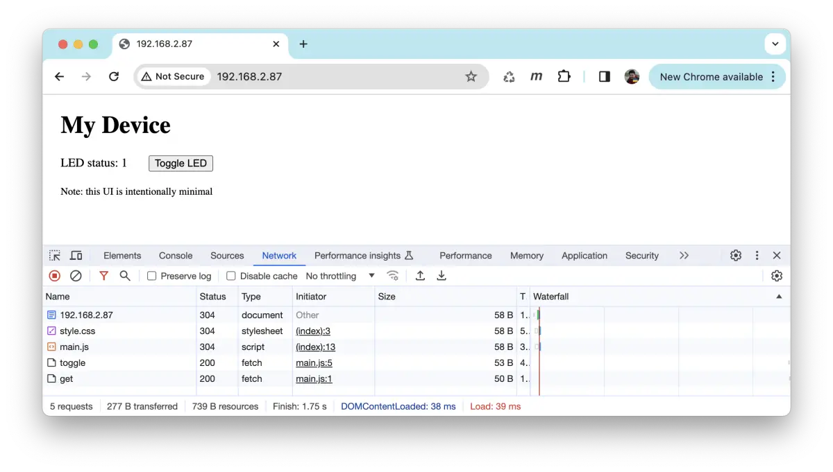
And here is the step-by-step explanation on the flow of requests:

REST API
The RESTful server API provides the following authenticated endpoints:
/api/login- logs the user in, setting the access token; returns user name as a JSON object/api/logout- logs the user out, clearing the access token/api/debug- sets Mongoose debug level from a JSON object/api/stats/get- returns statistics (variable values) as an array in a JSON object/api/events/get- returns the event log as an array of JSON objects/api/settings/get- returns the device settings as a JSON object/api/settings/set- sets the device settings from a JSON object
SSL/TLS (HTTPS) support
To build with Mongoose built-in TLS support, just do
make CFLAGS_EXTRA="-DMG_TLS=MG_TLS_BUILTIN"
In order to build with mbedTLS support, run:
make TLS=mbedtls
Once the executable is rebuilt and is running, you can point your browser to https://localhost:8443 to access the Web UI via HTTPS.
Note: the example uses a self-signed certificate, thus, your browser will show a security warning. Ignore the warning and proceed to the Web UI
Check the "How to build" section of the TLS tutorial for specific information on other building options for your OS
Backend implementation
Let's now dive into the internals of how to build a device dashboard like this one. We'll start from the server backend, running on the device itself.
UI files and embedded filesystem
When you connect your browser to http://localhost:8000, it will ask to GET the index file, which contains references to JavaScript files, including the Preact code, and images. All these are static files and are served by the static server section of our hybrid server architecture. The event handler function calls the mg_http_serve_dir() function when it receives an MG_EV_HTTP_MSG event for a non-API URI:
static void fn(struct mg_connection *c, int ev, void *ev_data) {
  ...
  if (ev == MG_EV_HTTP_MSG) {
    if (mg_match(hm->uri, mg_str("/api/#"), NULL)) {
    ...
    } else {
      struct mg_http_serve_opts opts = {...};
      mg_http_serve_dir(c, ev_data, &opts);
    }
  }
}
All the web files can be embedded in a packed filesystem (more information on the embedded filesystem tutorial). For this example we've chosen not to do so, this way the developer can work on the web files serving them on a computer, and embed them later when deploying to an embedded device
In fact, this example suggests a productive way to develop a UI for an MCU: develop it on a workstation using stubs for the hardware API, then just build on the MCU.
Auth and login
The JavaScript code will try to GET /api/login, which requires authorization. If it fails, it will present the login screen. Once you enter your credentials, it will GET /api/login again but this time using the authorization headers. If user and password are valid, the server will return a token that can be used for further accesses. A logout clears the token. In the next section we'll see how these functions get called.
The hybrid server handles authorization by checking for a valid user and denying all /api/ URIs in case there is not.
User credentials are extracted from the headers using the mg_http_creds() function. This code snippet shows a simple way of doing user authentication, valid for the purpose of this example:
RESTful API
The RESTful server makes use of mg_match() for URI matching, and mg_http_reply() to generate responses. Here, the %m extension, through the macro MG_ESC(), calls mg_print_esc() that simplifies printing JSON strings.
Take a look at the JSON-RPC tutorial for details on how to use Mongoose's built-in JSON and RPC APIs.
main() and init
The main() function maintains a structure similar to that of an HTTP server, in which we just initialize an event manager and
start the event loop, as usual.
The function web_init() takes care of initializing the HTTP listener and the periodic timer that will start an SNTP request to get current time
Frontend implementation
This is an integration tutorial, for more details on some of the techniques used here consult the tutorials in the Web UI section, or those referenced further on in this text.
As we've seen above, all frontend files are read from disk in this example, with the idea of being embedded on a packed filesystem when deploying to an MCU. In order to pack some of the JavaScript files, npm needs to be installed.
Overview
The UI is developed using the Preact framework, an alternative to React with the same modern API and a smaller footprint, ideal to fit on small devices with limited room for flash memory. Once served via the HTTP server, it will run on the browser.
On a content refresh, each section fetches its corresponding RESTful API endpoint to get the data it will render on screen:
The settings handling section will POST to the /api/settings/set URI the new config on a button press:
For more detailed information on working with Preact, check the Preact-based UI tutorial
Login process
- The initialization section tries to GET the
/api/loginURI with no authorization headers; if it fails, it will render the login screen
- When credentials are entered at the login screen, the following GET will use proper authorization headers
- Once the REST API grants access and returns the user token; this token will be utilized for all remaning API transactions. A logout simply calls the REST API function that clears the token
For more detailed information on the login process, check the Web UI login tutorial