


CubeIDE Mongoose Integration
This tutorial is a step-by-step guide on how to build a Mongoose-based Web UI dashboard on a NUCLEO development board using the STM32CubeIDE development environment. We provide instructions for NUCLEO-F746ZG, NUCLEO-F429ZI, and NUCLEO-H743ZI2.
Create a new Cube project
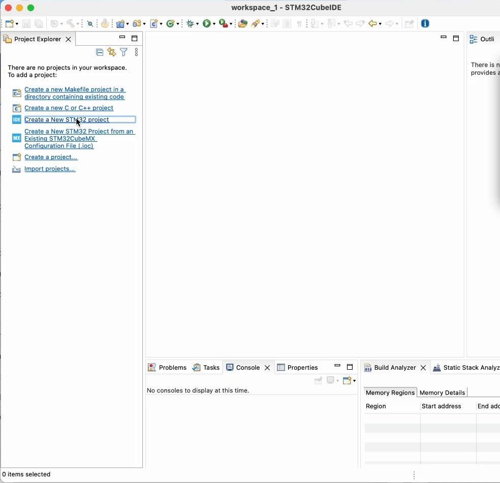
Start STM32CubeIDE and create a new project. If you have an empty workspace, click on "Create a New STM32 project":
Otherwise, follow the menu File -> New -> STM32 Project.
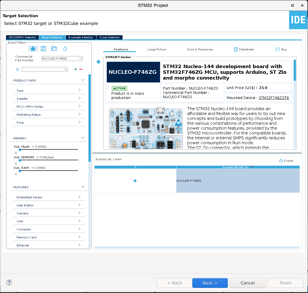
The target selector will open, here we can mainly select an MCU/MPU (like the STM32F746ZG) or a board (like the Nucleo-F746ZG). The easiest way, if you have a commercial development board, is to go with it. If you are developing on a custom board, then choose your device.
If you go with the board initialization, choose the Board Selector tab, type and select your board commercial part number, e.g.: NUCLEO-F746ZG, then click Next. You'd probably want to mark it as favorite, as you will be making several projects for it.
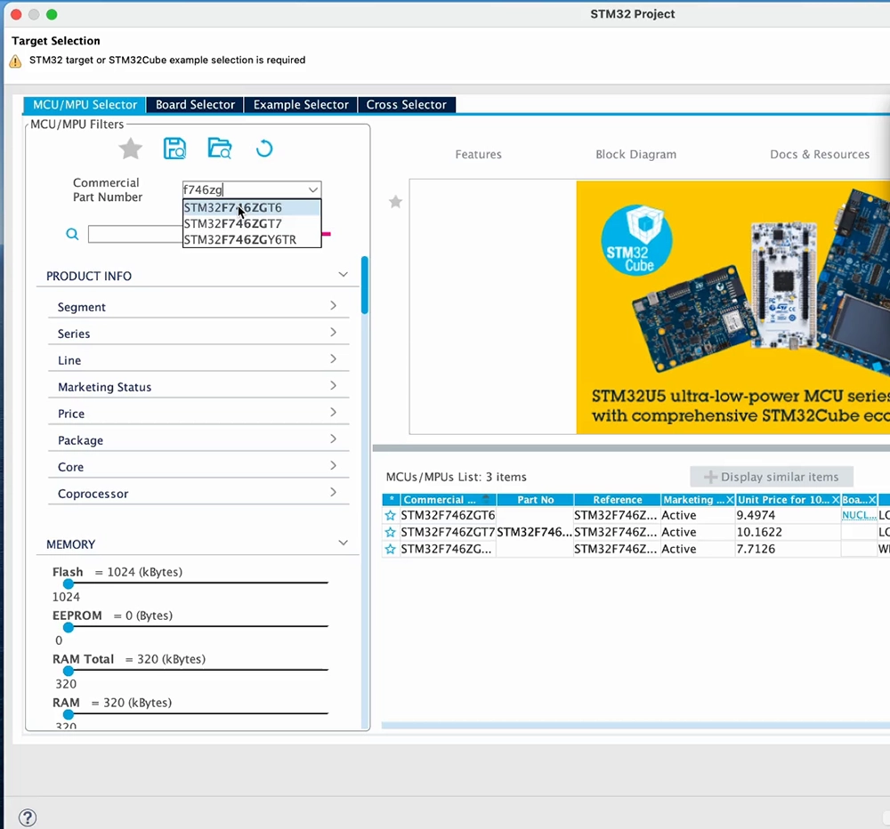
If you go with the device selection instead, choose the MCU/MPU Selector tab, then type and select your device commercial part number, e.g.: STM32F746ZGT6, then click Next
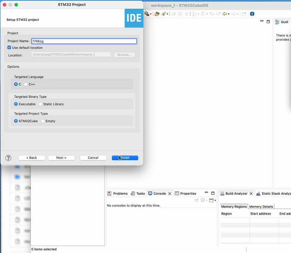
Pick a name for your project, and check the project location. This will be a C language project in which we'll generate an executable. Click Finish:
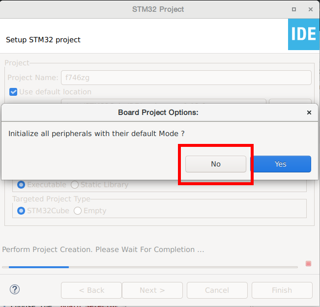
If you chose the Board Selector, Cube will ask if you want to initialize all peripherals to their default mode, answer No. We just need it to configure our GPIOs and avoid generating unnecessary driver code.
If you chose the MCU/MPU Selector, we'll be configuring necessary GPIOs as we need them.
If this is your first time with Cube or this device family, Cube will download the firmware package, containing the HAL for this device family, and install it after you agree to its license terms and conditions. We are now ready to go.
Blink the blue LED
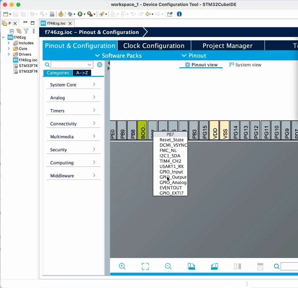
At the device configuration wizard, we'll configure the proper GPIO pin as an output. The blue LED in the Nucleo-F746ZG and Nucleo-F429ZI boards is connected to GPIO PB7, so click on pin PB7 and choose GPIO_Output. Skip this if you created the project through the Board Selector, choose the proper pin for other boards:
On the Nucleo-H743ZI2 board, the LED is yellow and is connected to GPIO PE1.
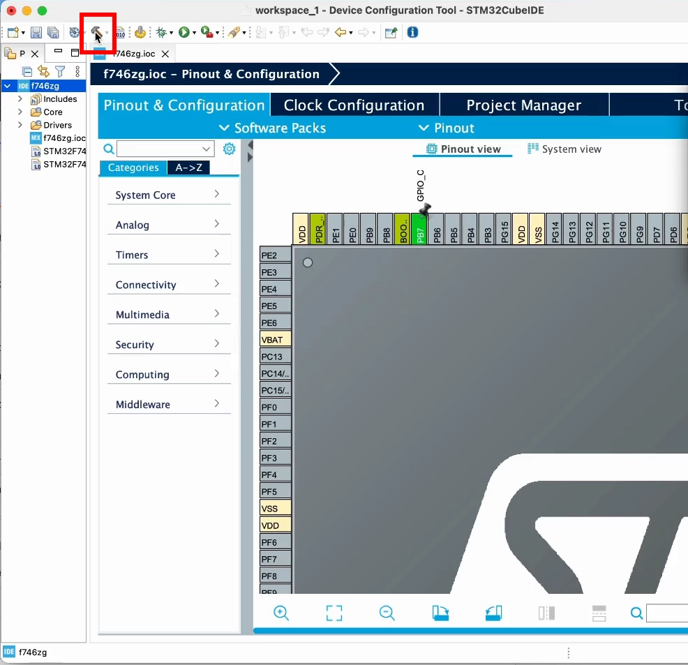
Now select the project and click on the hammer icon, that will generate the base project structure.
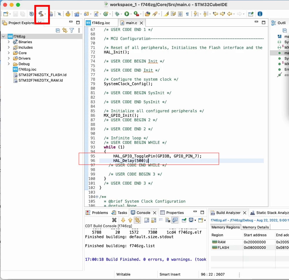
Once this is done, we can write our blink code in Core/Src/main.c. Using Cube HAL functions we'll toggle the pin and wait for 500ms inside the main loop:
HAL_GPIO_TogglePin(GPIOB, GPIO_PIN_7);
HAL_Delay(500);
Click on the hammer icon again, that will build the project:
Now click on the green arrow icon, accept the debug configuration, and your board will be flashed with this code. You should soon see the blue LED start blinking
Send text to USART3
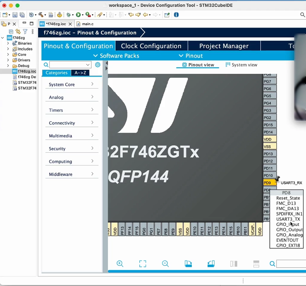
These boards have a built-in ST-Link debugger, which also provides a USB serial port wired to PD8 and PD9. These pins can be used by USART3.
At the device configuration wizard, click on pin PD9 and choose USART3_RX. Then click on pin PD8 and choose USART3_TX. Skip this if you created the project through the Board Selector:
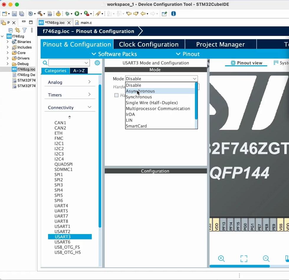
Click on Connectivity, then on USART3, and finally select Asynchronous mode, as we'll be using it as a UART:
For some chips, for example the H743, you may have to "resolve clock issues", that is, allow Cube to find a suitable clock configuration. We'll see this in more detail later.
Click on the hammer icon, that will re-generate the base project structure and re-build it.
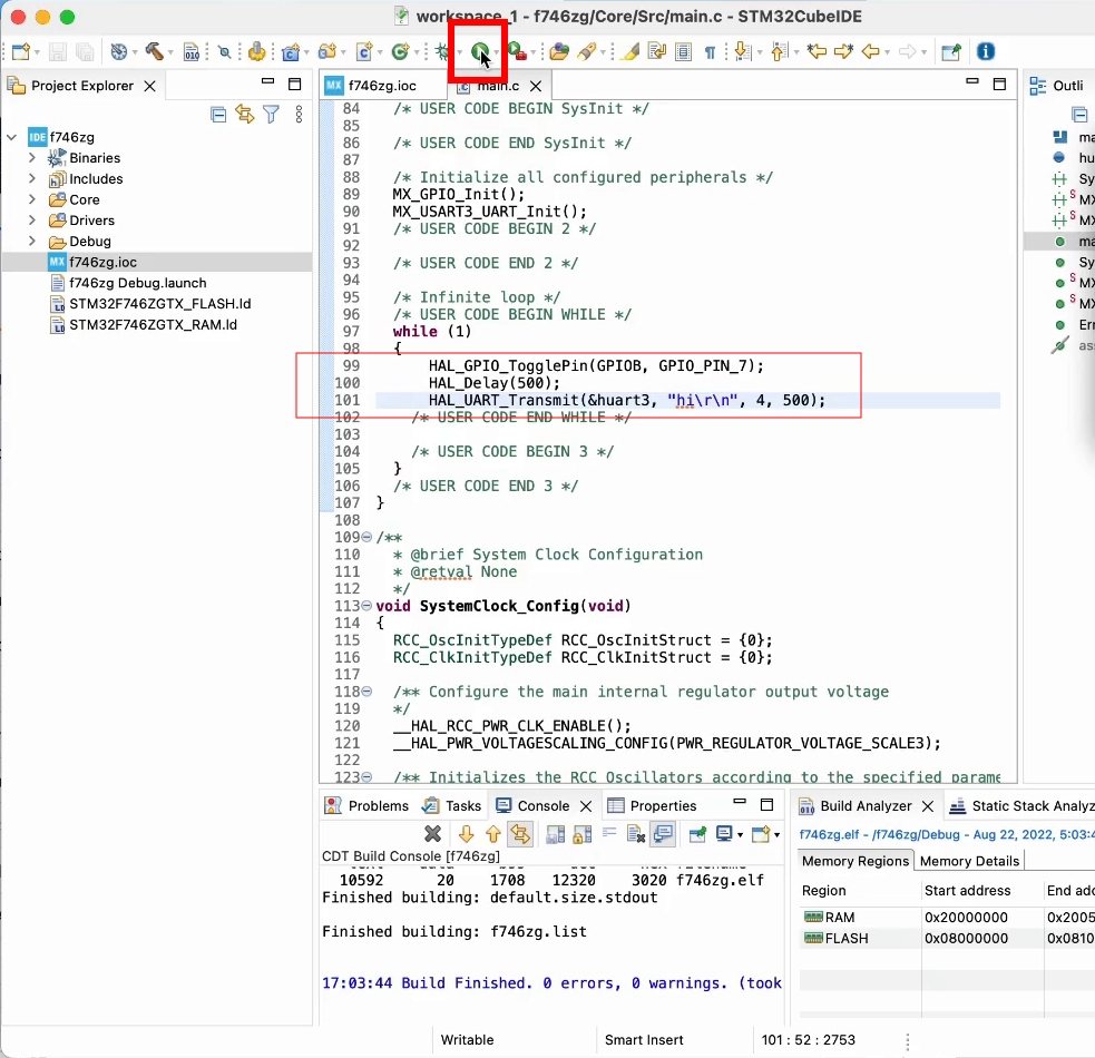
Once that is done, the default code in CubeIDE has already included the USART setup and this defaults to using 115200 bps. let's add UART output to our code using one of the Cube HAL functions:
HAL_UART_Transmit(&huart3, "hi\r\n", 4, 500);
Click on the green arrow icon, this will build the project and flash your board:
With the terminal software of your choice, open the proper USB serial port at 115200 bps and you'll see the board greeting you:
picocom /dev/ttyACM0 -i -b 115200
...
hi
Redirect printf() to UART
This will not only allow us to print texts in a simpler way, but also use printf() for debug output, which will enable Mongoose log output further on.
In your main.c, implement _write() function before main() in the user code block:
// Redirect `printf()` to UART so debug output is visible:
int _write(int fd, unsigned char *buf, int len) {
  HAL_UART_Transmit(&huart3, buf, len, HAL_MAX_DELAY);
  return len;
}
Change the UART output to use printf():
printf("hi 2\r\n");
Click on the green arrow icon, this will build the project and flash your board. With the terminal software of your choice, open the proper USB serial port at 115200 and you'll see the board greeting you:
picocom /dev/ttyACM0 -i -b 115200
...
hi 2
Change system clock frequency
The board configuration defaults to setting the microcontroller to run from its HSI clock, that is, at 16 MHz for the F4 and F7 and 64 MHz for the H7 series. However, these microcontrollers are able to run at higher speeds using their internal PLL.
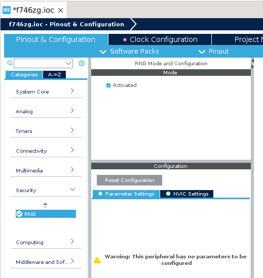
Even though we won't use the Random Number Generator (RNG) peripheral in this tutorial, it affects the way the clock chain is setup, so we'll enable it first and get ready for other examples using it.
To enable the RNG peripheral, at the device configuration wizard, click on Security, then on RNG, and finally check Activated
Now let's set the system clock, for the H7xx see this appendix:
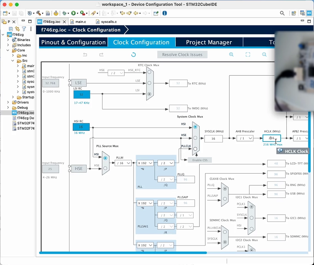
At the device configuration wizard, select the Clock Configuration tab. Within the block diagram, change HCLK to the device maximum frequency, see table below:
| Board | Device | Max Clock Frequency |
|---|---|---|
| NUCLEO-F429ZI | STM32F429ZIT6 | 180 MHz |
| NUCLEO-F746ZG | STM32F746ZGT6 | 216 MHz |
The following screen snapshot shows doing it for the F746, to 216 MHz:
The wizard will inform us that it can't solve that with the current configuration, and ask to find a solution using other sources. Accept the suggestion and it will automatically configure the PLL:
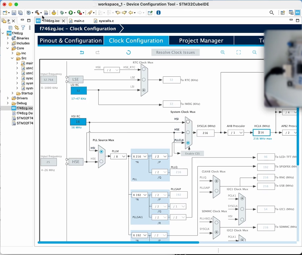
Click on the green arrow icon to build the project and flash your board; the blue LED should blink again and the microcontroller will be running now at its maximum clock frequency
The STM32Cube HAL requires a time base; it defaults to using the SysTick. For projects using an RTOS, as these usually take over the SysTick, it is good practice to select a different source.
To change the timebase source, at the device configuration wizard, select the Pinout & Configuration tab. Click on System Core, then on SYS, and finally select TIM6 as Timebase source:
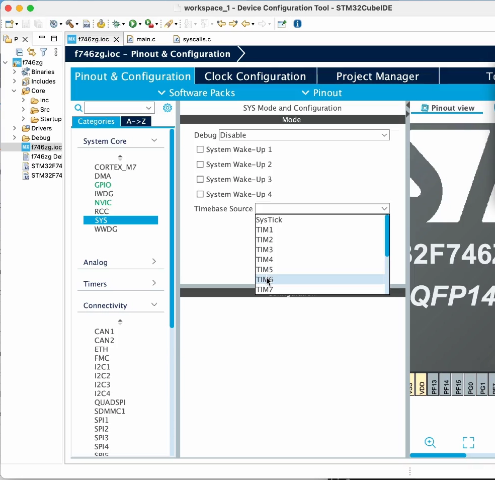
Note: In multicore devices, to be able to use this timer from the Cortex-M7 core requires first assigning
TIM6to theM7core. Also,SYScan also be namedSYS_M7and there will likely be aSYS_M4too (for Cortex-M7 + Cortex-M4 dual-core devices, for example).
Enable the Ethernet controller
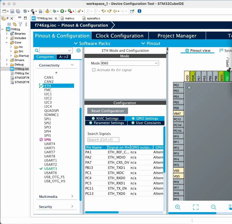
At the device configuration wizard, select the Pinout & Configuration tab. Click on Connectivity, then on ETH, and select Mode as RMII. Then on the NVIC Interrupt Table section enable the Ethernet global interrupt:
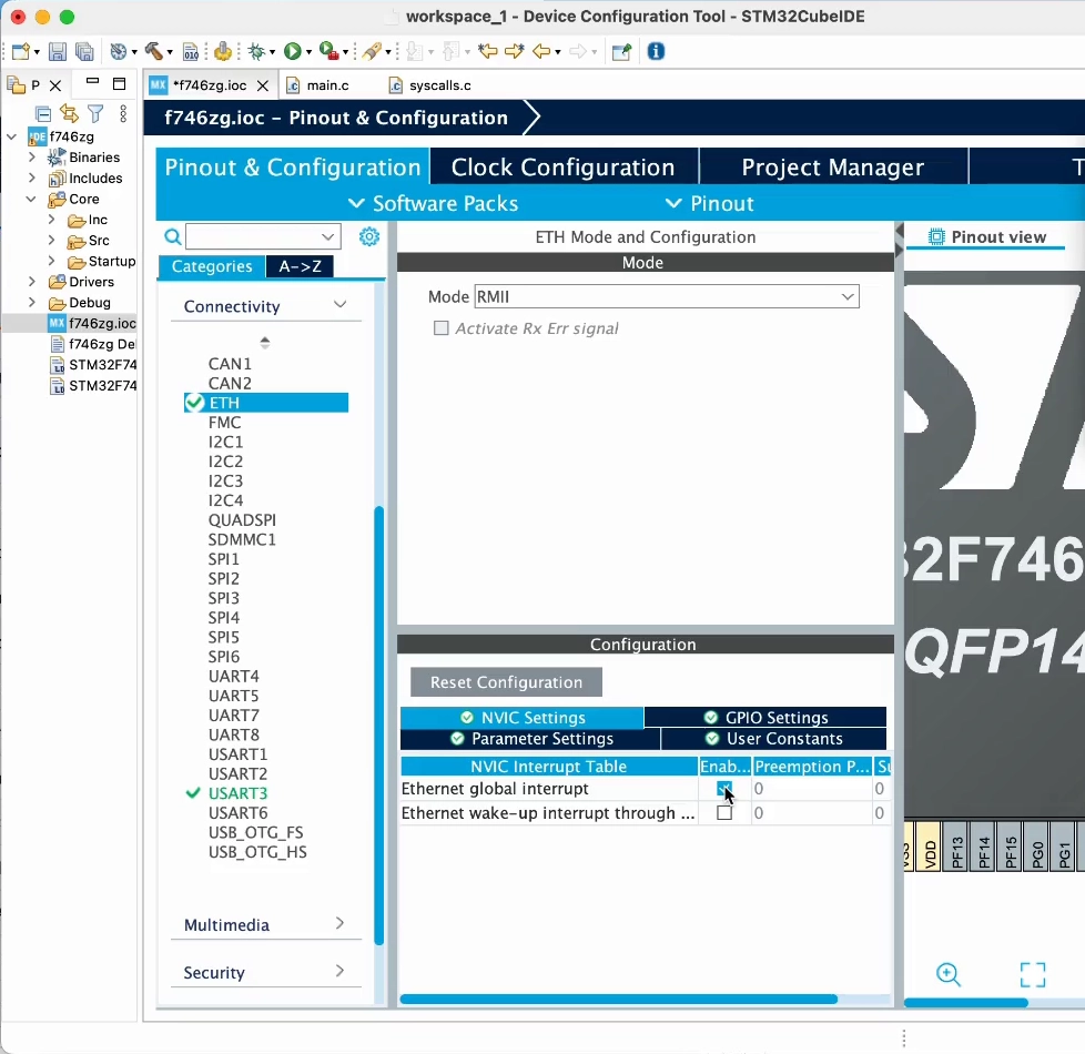
In projects where we won't be using the ETH HAL driver (in this tutorial or in any other project where we use Mongoose built-in TCP/IP stack):
You can save some RAM by configuring Rx Buffer Length as 0 in the Parameter Settings section.
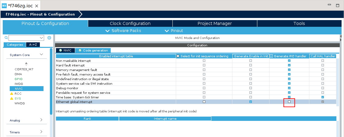
Disable generation of the ETH IRQ Handler. Click on System Core, then on NVIC, then on the Code Generation section disable Generate IRQ Handler for the Ethernet global interrupt:
If you created this new project for a board, that is, using the Board Selector, the GPIOs will automatically configure for it, so you can skip this step.
If you, instead, have used the MCU/MPU Selector, then go to the GPIO Settings section and set the RMII pins to those corresponding to your board. The Nucleo-F746ZG and Nucleo-F429ZI boards are based on the MB1137 design, and its user manual is UM1974. The Nucleo-H743ZI2 board, instead, is based on the MB1364 design, and its user manual is UM2407 (The former Nucleo-H743ZI board was based on MB1137). For these boards we need to click on PG11 and PG13 and configure them as ETH_TX_EN and ETH_TXD0, respectively.
Click on the hammer icon, that will re-generate the base project structure and re-build it, adding support for the MAC controller.
Integrate Mongoose
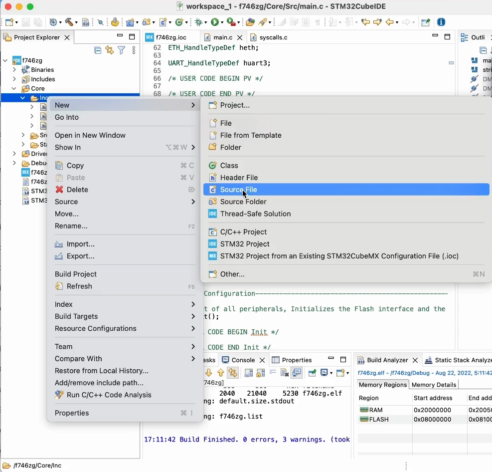
Download mongoose.h and mongoose.c into Core/Inc/ and Core/Src/, respectively. Create new files, the header mongoose.h in Core/Inc/ and the source mongoose.c in the Core/Src/ folder; and paste contents there:
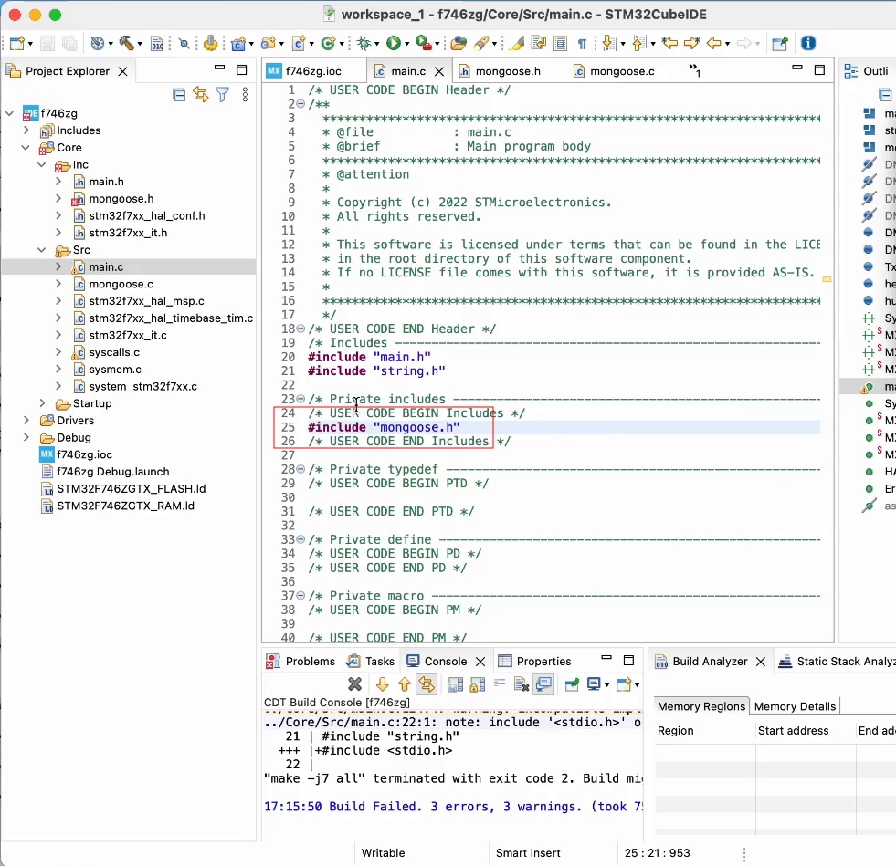
Include mongoose.h so we can call Mongoose API functions
Now we need to tell Mongoose in which architecture it is running. This is done by defining the macro MG_ARCH; and when this symbol is not defined and there is no other clue, Mongoose will default to try to include mongoose_config.h. Let's create this file and add this content to it:
#pragma once
#define MG_ARCH MG_ARCH_CUBE
Finally, in Core/Src/main.c, inside the main() function, we'll initialize Mongoose:
struct mg_mgr mgr;
mg_mgr_init(&mgr);

for (;;) {
  mg_mgr_poll(&mgr, 10);
}
Click on the green arrow icon to build the project and flash your board; since our infinite loop is now before the one toggling the LED, the blue LED will not blink
With the terminal software of your choice, configure it for 115200bps. Open the proper USB serial port and you'll see Mongoose log. Once the DHCP server in your network assigns an address to your board, you'll see it:
picocom /dev/ttyACM0 -i -b 115200
...
b4e 2 mongoose.c:6382:onstatechange     READY, IP: 192.168.2.10
If you ping this address, it should respond.
Implement a simple web server
Let's modify Core/Src/main.c to add a very simple web server; it will just respond with "ok" to any URI you request.
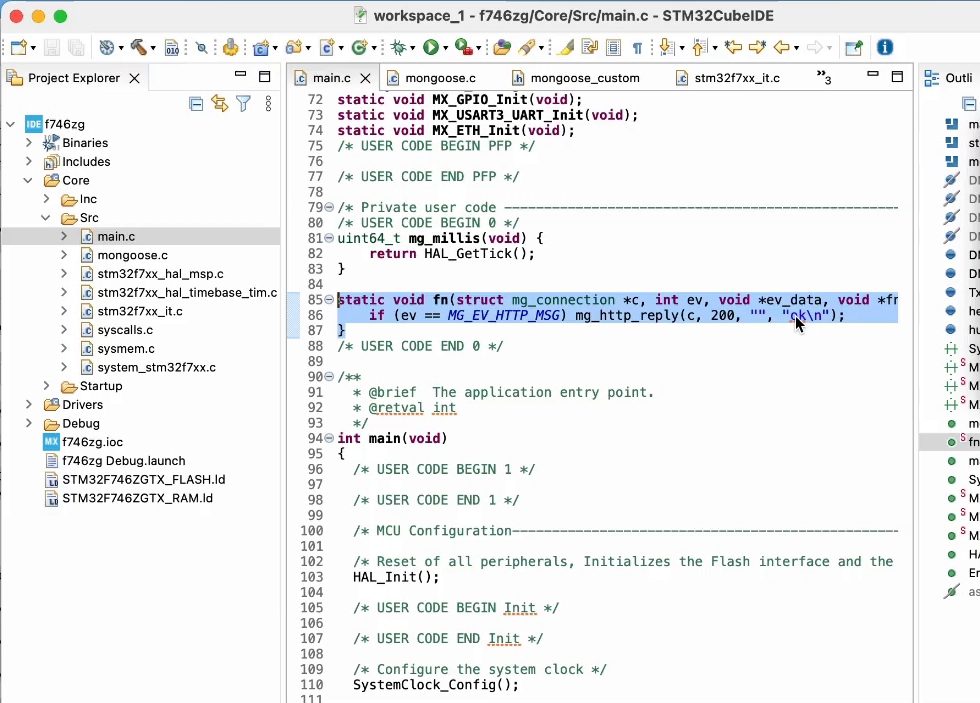
Outside of the main() function, add the HTTP event handler, this function will be called when the event manager processes an HTTP message:
static void fn(struct mg_connection *c, int ev, void *ev_data) {
  if (ev == MG_EV_HTTP_MSG) mg_http_reply(c, 200, "", "ok\n");
}
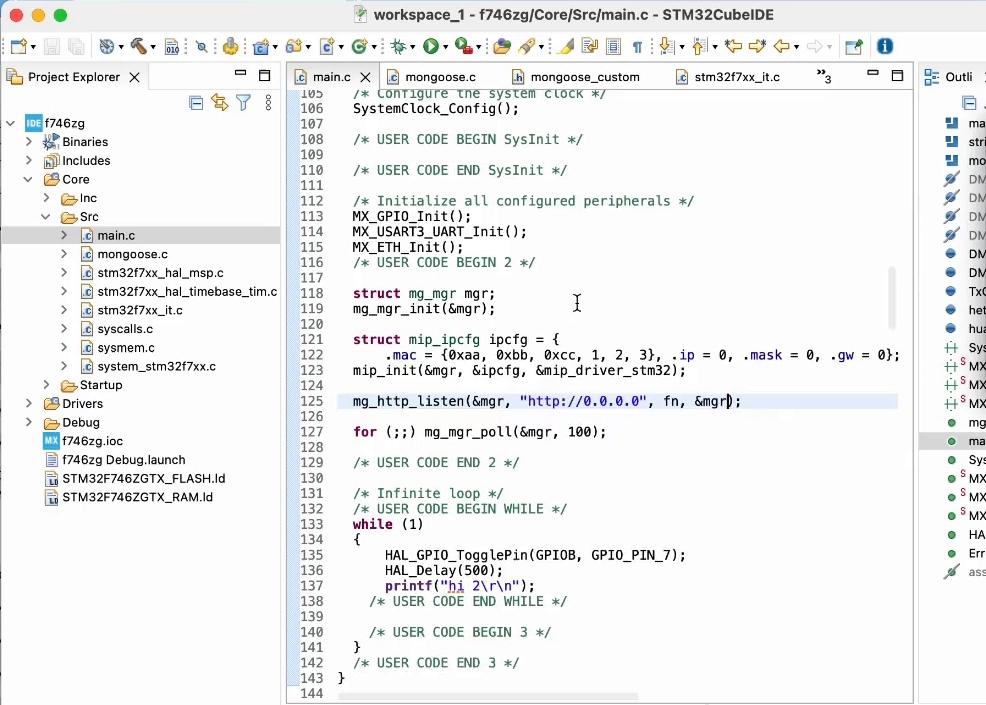
Finally, also in Core/Src/main.c but inside the main() function, we'll add an HTTP listener on any address. We do this after the event manager initialization and of course before the infinite loop. Passing a pointer to the former function fn as a parameter, we instruct the event manager to call this event handler for that:
mg_http_listen(&mgr, "http://0.0.0.0", fn, &mgr);
Click on the green arrow icon to build the project and flash your board
Once the DHCP server in your network assigns an address to your board, you'll see it in the log; it should be the same as before, anyway.
Point your browser to http://IP_ADDRESS, where IP_ADDRESS is the board's IP address; you'll see the "ok" message
This is of course a very simple and limited example, but is also the cornerstone on which to build a RESTful server.
Add full Web Dashboard
Mongoose provides a Web UI builder tool which allows to build Web UIs easily with no frontend skills required.
Go to Web UI builder, start a new project, select destination directory where your project lives.
Choose the board, default dashboard template, click finish.
Click generate button on the top right - do not cleanup the destination when asked. That should create mongoose directory in the project. Remove mongoose.c and mongoose.h files that we have added, then right-click on the project, choose "New / Folder" and select the generated mongoose folder. When done, right-click on it and select "Add / remove include path".
In the main() function, replace mongoose initialisation with this:
mongoose_init();
for (;;) {
  mongoose_poll();
}
Rebuild and reflash - add see the dashboard running by your device!
From this point on, it is easy to update your dashboard using the Web UI builder.
For next steps, see example videos and Web UI Builder documentation.
Integrating into existing Cube projects
Now you are ready to start trying ready-made examples to develop your own code based on them. For that, you need to import these examples into your workspace.
We'll import one of the examples present in the Mongoose git repository:
Follow the Build Environment to setup git.
Start a terminal in the project directory and clone the Mongoose Library repo:
git clone https://github.com/cesanta/mongoose
Now we are ready to import a project:
Start STM32CubeIDE.
If you have an empty workspace, you can click on Import projects...
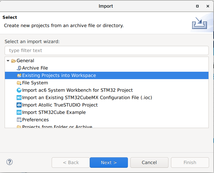
Otherwise, follow the menu File -> Import..., then open General and select Existing Projects into Workspace; then click Next:
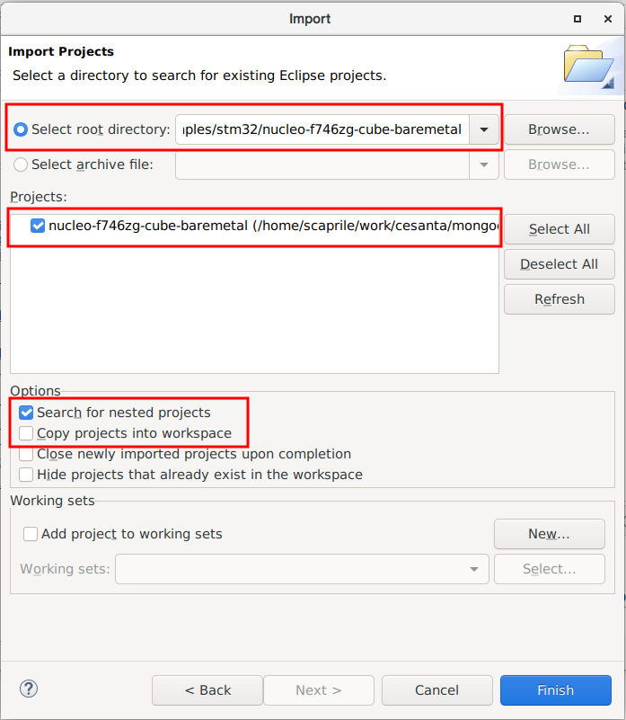
Pick the project directory of your choice as root directory, make sure that the project is recognized and checked. As the repository uses symbolic links, do not copy the files, let Cube just import the Project where it is. Click Finish:
Click on the project in the Project Explorer tab, you are all set.
Set H7xx clock frequency
Some high-performance microcontrollers include the option to work with a Switched Mode Power Supply (SMPS) or a Low-Dropout Regulator (LDO). This responds to performance reasons, and requires setting device registers according to the hardware being used.
Some boards like some Discovery and NUCLEO for H745, H747, H755, for example, are hardwired to work with the SMPS, requiring solder jumper changes to able to work with the LDO. In the aforementioned devices, working with the LDO allows a maximum clock frequency of 480Mhz, while using the SMPS is limited to 400 MHz.
Note: Check your board reference manual before changing the power settings and don't exceed the maximum working frequency.
Set H743 clock frequency
The H743 is quite a complex microcontroller, with several clock domains feeding a diversified network of internal buses.
At the device configuration wizard, click on System Core, and then on RCC. Then on the Parameter Settings section make sure Power Parameters -> Power Regulator is set to Power Regulator Voltage Scale 3, as high speeds require the highest CPU operating voltage. Then configure System Parameters -> Product revision to the correct revision number for your chip, see table below:
| Board | Device (Rev) | Max CPU Clock Frequency | Max HCLK Frequency |
|---|---|---|---|
| NUCLEO-H743ZI | STM32H743ZIT6 (Y) | 400 MHz | 200 MHz |
| NUCLEO-H743ZI2 | STM32H743ZIT6 (V) | 480 MHz | 240 MHz |
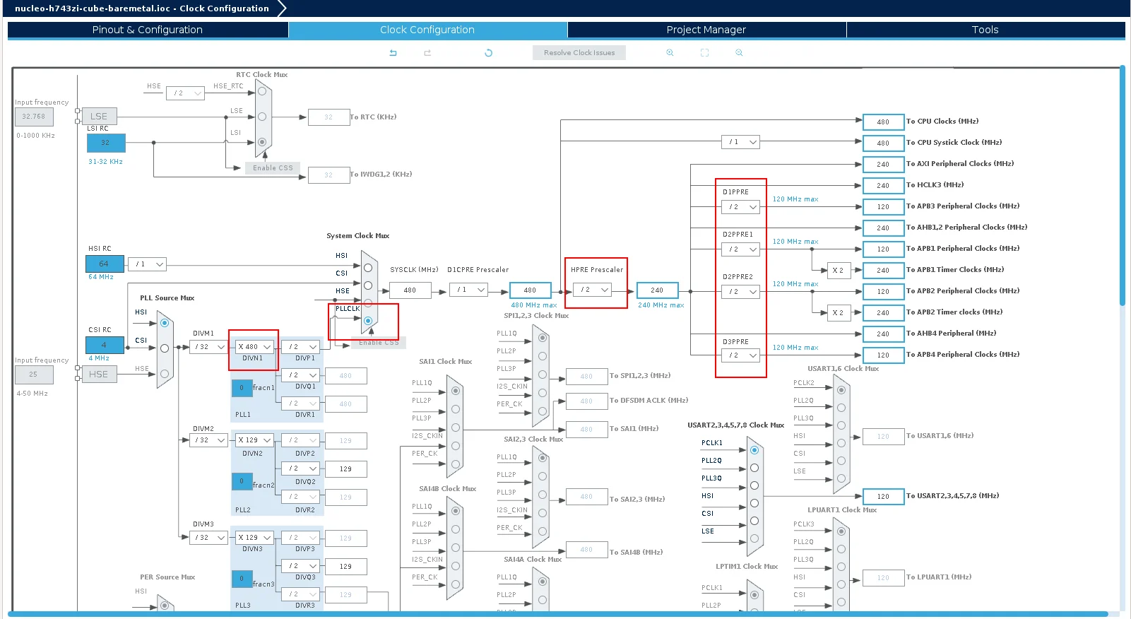
Then, at the device configuration wizard, select the Clock Configuration tab. Within the block diagram, change the HPRE prescaler to /2, then set the System Clock Mux to the PLLCLK; set DIVN1 within the PLL1 to your device maximum CPU clock frequency (see table above), and finally fix all domain prescalers setting D1PPRE, D2PPRE1, D2PPRE2, and D3PPRE to /2. In the Cube versions we tried, the automatic solver did not work properly, so resist the temptation to use it.
For revision 'Y' chips, you may also need to set the fractional part of the PLL divisor to 0.
Handling I-Cache and D-Cache
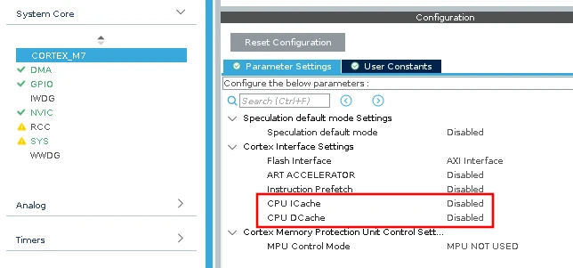
Mongoose Ethernet drivers use the Ethernet controller and its DMA engine at the register level. Our baremetal examples intentionally do not enable and even disable any caches in the microcontroller. Our Cube projects do the same.
In your projects, disable CPU I and D caches:
If you really want to use the caches, in particular the D cache, you can
- if possible, setup a memory area that is non-cacheable (preferred)
- our STM32H driver handles cache invalidation and flushing
For more information, please read STM32 Ethernet and caches